|
Articles
30 Dec 2011 NURBS and CAD: 30 Years TogetherDmitry Ushakov
In the outgoing year engineering celebrates a remarkable anniversary – thirty years of industrial use of Non-Uniform Rational B-Spline (NURBS) for modeling 3D curves and surfaces. In August 1981 an American aircraft concern Boeing proposed to embody NURBS in IGES industrial standard. Although the decision was officially approved only a couple of years later, CAD industry reacted to this proposal at once: the same year SDRC and Computervision - the two leading vendors of engineering software – announced their support for NURBS. Today, thirty years later, it is practically impossible to find any CAD that does not support NURBS. What is the reason for such a phenomenon? Why inventing NURBS revolutionised the industry? Below I try to give answers to these questions, and remember all researchers who contributed to development and establishment of NURBS.
Sculptured Surfaces
It is well known that research studies of 3D geometric modeling started as part of CAM (computer-aided manufacturing) rather than CAD (computer-aided design). Inventing NC (numerically-controlled) machine tool at the beginning of the 1950s at MIT (Massachusetts Institute of Technology, US) generated demand for digital mock-up of component parts, required to develop control programs for machine tools. Various research groups studied the principles of modeling 3D objects; their main customers were the largest companies in aerospace and car-manufacturing industries.
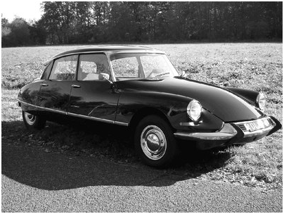
Fig. 1. Citroën DS
Take a look at the picture of Citroën DS (YOM 1955-1975), which became an all-time car icon. Accurate fabrication of such complex sculptured surfaces requires advance mathematical apparatus, and it’s certainly not a coincidence that one of the first studies in this field was conducted by a French mathematician Paul de Casteljau who worked for Citroën. He suggested a method for construction of smooth curves using a set of reference points that determine geometric properties. The results of his research were published only in 1974; but the study was completed as far back as 1959, which affords grounds to consider Paul de Casteljau to be the author of curves and surfaces that are now known under the name of another Frenchman - Pierre Bézier. But before talking more about him, let me remind you of the agenda associated with “sculptured” engineering surfaces.
How is it possible to constructively (by geometric construction rather than abstract algebraic equations) define a smooth surface of a required esthetic shape? The simplest method is to specify four points in a 3D space, which form a so-called bilinear patch:
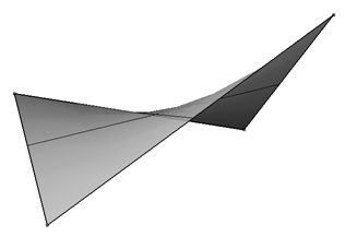
Fig. 2. Bilinear patch
A bilinear patch is a type of a ruled surface that fully consists of linear segments connecting corresponding points of two curves:
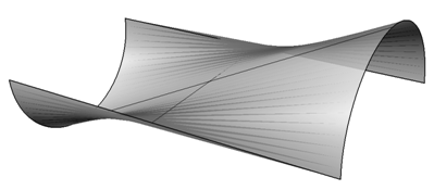
Fig. 3. Ruled surface
An MIT professor Steven Coons summarized such representation method for double curves surfaces that are named after him (Coons patch):
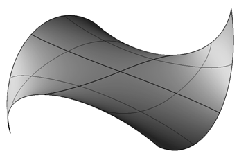
Fig. 4. Coons patch
In 1967 he published a treatise “Surfaces for Computer-Aided Design in Space Form” [Coons 1967], which became widely known as the “Little Red Book”. His techniques for boundary curves and blending functions formed the basis for further research in the field. Coons was the first to propose using rational polynoms to model conic sections. Coons’ outstanding contribution in CAD development is even more emphasised by the fact that he was an academic supervisor of Ivan Sutherland, the creator of a famous Sketchpad, which became the prototype of modern CAD systems.
Bézier Curves
Coons patch allowed controlling the surface shape on its boundaries but not between the boundaries. Pierre Bézier, who at the beginning of the 1960s was developing UNISURF system for designing surfaces of Renault cars, clearly understood the importance of controlling shape on the inside.
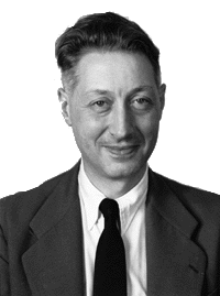
Fig. 5. Pierre Bézier
Pierre Bézier, a true representatives of the French mathematical tradition, was well aware of the works of Charles Hermite (a French mathematician of the XIX c.); in particular, cubic curves named after him. Hermite curve is a geometric representation of a cubic curve using end-points and tangent vectors. The shape of a Hermite curve can be controlled by varying vector directions and sizes:
Fig. 6. A family of Hermite curves
Bézier was not happy that defining Hermite curves one could only specify its conduct in end-points but could not explicitly influence the curve shape between such points (in particular, a curve can arbitrary move away from the segment connecting its end-points). Therefore, Bézier designed constructively defined curve (that later was given his name), the shape of which can be controlled in intermediary, the so-called control points. Bézier curve always comes from the first reference point, touching the first section of a polygonal curve that connects all reference points, and ends in the last reference point, touching the last section. Any point on a polygonal curve always remains inside a convex closure of a set of reference points:
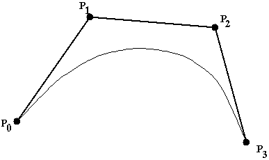
Fig. 7. Bézier curve with four control points
Bézier published his work on curves in 1962, but when 12 years afterwards Citroën took the wraps off its studies, it became clear that Paul de Casteljau had known about such curves at least three years before Bézier. De Casteljau described them constructively, and the algorithm was named after him.
Later Forrest showed connection between Bézier curves and Bernstein polynomials (of which mathematicians knew as far back as from the beginning of the XX c.) He demonstrated that the function that defines Bézier curves can be represented as a linear combination of basic Bernstein polynomials [Forrest 1972]. It enabled studying the properties of Bézier curves relying on the properties of these polynoms.
There are two methods to move from curves to Bézier surface. The first method introduces the so-called generating Bézier curves that have identical parameterisation. With each parameter value, a Bézier curve is constructed using points on such curves. Moving along generating curves, one constructs a surface that is called a rectangular Bézier surface. The area for specifying surface parameters is rectangular. The second method uses natural generalization of Bernstein polynomials in the case of two variables. A surface defined by such a polynom is called a triangle Bézier surface.
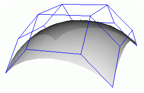
Fig. 8. Bézier surface
Splines
Being impeccable geometric constructs, Bézier curves and surfaces, however, have a couple of properties that considerably restrict their applicability. One of such properties is that Bézier curves do not allow accurate representation of conic sections (for instance, of a circular arc). Another one is that their algebraic degree increases together with the number of reference points, which greatly complicates numerical calculations.
Mathematicians have long known the way to combat algebraic degrees of complex curves – it suffices to construct a curve from smoothly conjugated segments, each of which has a constrained algebraic degree. Such curves are called splines; the first reference to them was made by Isaac Schoenberg, an American mathematician of Romanian origin [Schoenberg 1946]. Carl de Boor, another American mathematician but of German origin, look at Schoenberg’s theoretical works from practical perspectives (in the CAD context). De Boor’s treatise “On calculating with B-Splines”[De Boor 1972] as well as a paper by Cox “The numerical evaluation of B-Splines” [Cox 1972], which was published the same year, established connections between a geometric shape of a compound curve and an algebraic method of its definition.
B-splines are generalizations of Bézier curves and surfaces: they enable defining a curve shape in a similar manner using reference points but an algebraic degree of a B-spline does not depend on the number of reference points.
The B-spline equation is similar to Bézier curves, but rather than being Bernstein polynomials, blending functions are defined recursively, depending on a parameter value. The range of definition of a B-spline parameter is divided into knots, in accordance with the conjunction points of algebraic curves of the given degree.
Inventing NURBS
The first work mentioning NURBS was a dissertation of Ken Versprille, a post-graduate student at Syracuse University, New York [Versprille 1975].

Fig. 9. Kenneth Versprille, the NURBS inventor
Versprille holds a bachelor of science degree in mathematics from the University of New Hampshire and then studied towards Master’s and Doctorate degrees at Syracuse University, where Steven Coons was his professor. Appreciating Coons ideas, Versprille published the first description of NURBS, which was the focus of his dissertation. Soon after the graduation, he was hired by Computervision as a senior programmer to develop a 3D modeling functionality in CADDS 3. Although his assignments (spline implementation) matched his research interests, his boss was more concerned with meeting the project deadline and insisted on rejecting NURBS in favor of using simpler (in terms of mathematics) Bézier curves.
Few years later, Versprille reached a top position at Computervision, and the company finally decided to support NURBS. A programer who was put in charge of the project sought Ken’s advice that was not late in arriving: “Just change a particular flag in a particular file from 0 to 1 and recompile the code!” Apparently, Versprille was working on NURBS from the very beginning, just not including the relevant code in a release. After a couple of errors were corrected, the code worked! [Yares 2008].
In 2005, Kenneth Versprille received Lifetime Achievement Award from CAD Society, a non-commercial CAD association, for inventing NURBS - an invaluable contribution to CAD development. Dr. Versprille received the award at a COFES (The Congress on the Future of Engineering Software) that took place the same year in Arizona.
Boeing Contribution
In 1979 the Boeing Company - an American aerospace corporation started developing its own CAD/CAM system called TIGER [Solid Modeling 2011]. One of the tasks of its developers was to choose an appropriate representation of 11 types of curves, comprising everything – from conic sections to Bézier curves and B-splines. In course of the project, one of the researchers – Eugene Lee – discovered that the main task (locating the intersection points of two arbitrary curves) can be narrowed down to solve a problem of locating the intersection point of Bézier curves, because any smooth curve within a certain neighbourhood can be approximated with a Bézier curve. It stimulated researchers to look for a way of representing all curves using a single shape. (It seems that they knew nothing of Versprille’s dissertation.)
Possibility to represent curves and other conic sections using rational Bézier curves became an important local discovery [Lee 1981]. Another step towards discovery was introducing non-uniform B-splines, well-known from scientific literature, into industrial practice. Finally, researchers integrated the two concepts into a single formula – NURBS. Afterwards, a great deal of efforts was needed to persuade other TIGER developers to start employing the unified representation for all types of curves.
Soon Boeing proposed to include NURBS in the IGES format and prepared a technical document with exhaustive description of a new universal type of geometric data. This proposal was received with great enthusiasm – first of all, due to a position taken by SDRC.
SDRC Contribution
In 1967 former professors of the Machine-Building Department of the University of Cincinnati (the USA) created SDRC (Structural Dynamics Research Corporation). Initially it was intended that the company would provide consulting services in machine-building, but with time SDRC transformed in one of leading global CAD developers. Starting with CAE (computer-aided engineering) the company then also turned to CAD (design), and developed I-DEAS, which helped to deal with a wide range of tasks – from conceptual design through wireframing and solid modeling to drafting, finite-element analysis and NC programming. I-DEAS was based on GEOMOD - an original solid modeler.
Initially GEOMOD represented solid bodies as polygonal meshes that approximate their boundaries. Having realised importance of the Boeing proposal to standardize NURBS, SDRC developers zealously took on implementing NURBS in GEOMOD. The algorithm was mainly developed by Wayne Tiller, who later co-authored a famous monograph "The NURBS Book" [Piegl 1997].
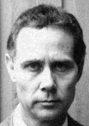
Fig. 10. Wayne Tiller, the President of GeomWare, and the co-author of "The NURBS Book"
I-DEAS ceased existing when in 2001 EDS acquired SDRC, while Wayne Tiller used his experience to implement NLib library (see below).
Contribution of GeomWare, IntegrityWare and Solid Modeling Solutions
An American company IntegrityWare has been developing libraries for geometric calculations since 1996. In 1998 it reached an agreement with Solid Modeling Solutions to develop SMLib – a solid modeling kernel, the first version of which was ready the same year.
SMLib is a sort of “nested-doll”, where every nesting level is a separate library of functions or classes. The most “nested-doll” is NLib - a library of functions (NURBS Library), developed by a partner company GeomWare. NLib is an exhaustive set of functions for designing and manipulating NURBS curves and surfaces. NLib algorithms are based on a classic monograph [Piegl 1997], and one of its authors - Wayne Tilleris is the founder and President of GeomWare. NLib is used by more than 85 companies involved in engineering software development.
An object-oriented library GSNlib (General Surface NURBS Library) is based on NLib; it is a set of methods for creating, editing, obtaining information and intersecting NURBS curves and surfaces. IntegrityWare distributed this library under the name of GSLib and licensed it to such companies as Robert McNeel & Associates (for developing Rhino 3D) and Ford Motor Company.
Subdivision Surfaces
Subdivision surfaces can be considered as polygonal models that are iteratively constructed from a base mesh; that with each iteration becoming closer to the shape of a modelled surface. The two components of a subdivision surface are the base mesh and the algorithm for smoothing it. Historically, the theory of subdivision surfaces started with the work of an American designer Chaikin, who developed a method of iterative curve construction according to reference points [Chaikin 1974]. Similar to Bézier, Chaikin starts constructing a curve with a characteristic polygonal curve defined by a set of reference points. At the next stage, a new sequence of reference points is formed, which is built under special rules based on the first sequence. Geometrically it looks like corner cutting of the initial curve – each section is divided in the 1:2:1 ratio and the angles between two sections are cut as new sections are put between the shortened, old ones. The process continues until the curve is not sufficiently smooth.
Fig. 11. Chaikin subdivision curve
Soon it was proved that the curve generated by the Chaikin algorithm is nothing else but a quadric uniform B-spline.
Chaikin method formed the basis for a family of algorithms developed by his followers. One of such algorithms was a method developed by Doo and Sabin for constructing quadric uniform B-spline surfaces using a base quadrangular mesh (each facet in such a mesh is a convex quadrangle) [Doo 1978]. Soon the researchers were able to extrapolate their method to any base mesh where each facet can have an arbitrary number of apexes – 3, 4, 5… Locally the resulting surface (except the finite number of points) is a quadric uniform B-spline. Doo - Sabin method is that at each step each facet is replaced with a smaller facet with the same number of apexes. Each apex of a smaller facet is the arithmetic average of the original apex, the centres of two adjacent edges and the facet centre. As a result, there is an unconnected mesh, where each new apex is then connected to all other apexes, obtained from the same old apex forming new facets. The resulting connected polyhedron is the basis for a new algorithm step. It’s easy to notice that this method as well as Chaikin method involves corner cutting:
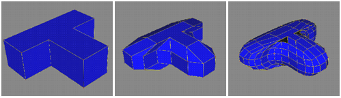
Fig. 12. Doo-Sabin subdivision surface
Post-graduate students at Utah Univestiy, Catmull and Clark, expanded the corner cutting method to construct uniform cubic B-splines [Catmull 1978]. Their method, like Doo - Sabin method, can work on base meshes of arbitrary topology (locally the resulting surface is similar to a cubic B-spline). The smoothing algorithm is based on iterative construction of a new mesh under somewhat different rules. The following figure illustrates how the method works:
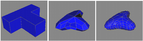
Fig. 13. Catmull-Clark subdivision surface
Subdivision surfaces constitute a convenient way of representing smooth surfaces in a compact manner. This property is broadly used to represent various organic objects, and, therefore, is also well suited to describe complex surfaces in surface modeling systems. (Special attributes are used to support non-smooth integrations – sharp edges, which limit the scope of subdivision algorithms.)
Currently several industrial standards for exchanging geometric data on the basis of subdivision surfaces are being developed.
Why NURBS are good?
Why have NURBS curves and surfaces played such an importance role in CAD development? First of all, they offer general mathematical representation for both analytical geometric objects and freeform curves and surfaces. Manipulating NURBS control points and weights enable flexible design of a great variety of geometric forms. Calculations with NURBS can be done rather quickly and are numerically stable. NURBS curves and surfaces have a clear geometric interpretation that is especially useful and valuable for designers who have a good knowledge of geometry. NURBS have a rich set of tools (knot insertion / removing / changing, increasing a degree, splitting), that can be used to create and analyse such objects. NURBS give invariants of scaling, rotating, translating, cutting, constructing parallel and isometric projections [Piegl 1991].
At the same time representation of curves and surfaces in NURBS has some disadvantages. First of all, it requires more memory: for instance, representing a circle as a NURBS-curve requires defining seven reference points and ten knots, which means saving 38 floating-point numbers instead of seven (centre, surface normal, radius). Incorrect weight function can result in extremely poor parameterisation, which will make further NURBS-based constructs impossible. Certain algorithms (for example, computing an intersection of two surfaces) work better in a traditional representation. Finally, some fundamental algorithms (such as inverse mapping) are numerically unstable in NURBS.
In spite of these shortcomings NURBS is still widely used in CAD – because noting better has been invented. Nevertheless...
T-Splines
T-splines – is a type of freeform surface similar to NURBS. The key difference between T-splines and NURBS is that reference points of a NURBS-surface must form topological similarity of a rectangular frame, while T-splines can have the so-called inner T-points (a reference point with three rather than four neighbors). T-splines serves as a bridge technology between NURBS and subdivision surfaces.
Fig. 14. T-spline
Modeling organic surfaces using T-splines reduces the number of reference points twofold in comparison with NURBS (with the same requirements for G2 surface smoothness).
T-splines were invented by Thomas Sederberg [Sederberg 2003]. In 2004 T-Splines, Inc. (the US) was formed to facilitate their commercial application; the company develops end-user software products using T-spline technology.
Time will show whether this patent-protected technology ousts NURBS. The recent acquisition of technology assets of T-Splines, Inc. by Autodesk [Autodesk 2011] demonstrated the recognition of this technology by CAD industry.
Bibliography
Autodesk, Inc., 2011, Autodesk Acquires T-Splines Modeling Technology Assets, http://news.autodesk.com/news/autodesk/20111222005259/en/Autodesk-Acquires-T-Splines-Modeling-Technology-Assets
Catmull, E., and Clark, J., 1978, Recursively generated B-spline surfaces on arbitrary topological meshes, Computer-Aided Design 10(6):350-355.
Chaikin, G., 1974, An algorithm for high speed curve generation, Computer Graphics and Image Processing, 3(4):346–349.
Coons S. Ŕ., 1967, Surfaces for Computer Aided Design of Space Form, MIT Project MAC, AUC-TR-41. http://publications.csail.mit.edu/lcs/pubs/pdf/MIT-LCS-TR-041.pdf
Cox, M. G., 1972, The Numerical Evaluation of B-Splines, J. Inst. Mathematics and Applications, Vol. 10, pp. 134-149.
De Boor, C., 1972, On Calculation with B-Splines, J. Approximation Theory, Vol. 6, No. 1, pp. 50-62.
Doo, D., 1978, A subdivision algorithm for smoothing down irregularly shaped polyhedrons, Proceedings on Interactive Techniques in Computer Aided Design, pp. 157-165.
Forrest, A. R., 1972, Interactive Interpolation and Approximation by Bezier Polynomials, Comp J., Vol 15, pp 71-79.
Lee, E. T. Y., 1981, A Treatment of Conics in Parametric Rational Bezier Form, Boeing document, Boeing, Seattle, Wash.
Piegl, L., 1991, On NURBS: A Survey, IEEE CG&A, Vol. 11, No. 1, pp. 55-71. http://www.ece.uvic.ca/~bctill/papers/mocap/Piegl_1991.pdf
Piegl, L. A., and Tiller, W., 1997, The NURBS Book, Springer.
Schoenberg, I. J., 1946, Contributions to the problem of approximation of equidistant data by analytic functions, Part A: On the problem of smoothing or graduation, a first class of analytic approximation formulas, Quart. Appl. Math. 4, 45–99.
Sederberg, T.-W., Zheng, J., Bakenov, A., and Nasri, A., 2003, T-Splines and T-NURCCs, ACM Transactions on. Graphics, 22(3), 477-484, http://cagd.cs.byu.edu/~tspline/innovation/papers/tspline.pdf
Solid Modeling Solutions, 2011, NURBS at Boeing. http://www.smlib.com/white%20papers/nurbsatboeing.htm
Versprille, K. J., 1975, Computer-Aided Design Applications of the Rational B-Splines Approxamation Form, doctoral dissertation, Syracuse Univ., Syracuse, N.Y.
Yares, E., 2008, A story about NURBS and bugs from Ken Versprille, http://www.evanyares.com/a-story-about-nurbs-and-bugs-from-ken-versprille/
See also:
Permanent link :: http://isicad.net/articles.php?article_num=14940

|