 |
Articles
26 Oct 2010 Synchronous Technology: The Third Attempt Dmitry Ushakov The paper was originally written in Russian and published at isicad.ru.
It is not meet to harness
Horse with trembling doe.
Alexander Pushkin, «Poltava»
The editorial board of isicad.ru regularly commits resources to test new capabilities of the latest versions of popular CAD and not less regularly shares its conclusions with the readers (see, for instance, “3D marches en masse with AutoCAD 2011”, “New gimmicks in Inventor 2011”, “;On-line KOMPAS-3D – in the isicad’s hands”). For long we have wanted to write a review of Solid Edge with synchronous technology. Unfortunately, our attempt to obtain an evaluation license for this product was not successful: representatives of the office of Siemens PLM Software in Russia refused to grant such license to us, explaining that staff members of the editorial board of isicad.ru also work for LEDAS Ltd., which sells its technologies and services to many CAD-vendors, including those who compete with Siemens. (We would like to state, however, that this does not prevent Siemens’ fruitful cooperation with our portal by placing its advertising and information materials with us).
Fortunately, Siemens does not refuse all those wishing to test its software. For instance, Deelip Menezes, the Head of SYCODE (a company that due to specific features of its products – data translation modules - maintains pretty close contacts with all CAD developers) and a well-known blogger, an active participant of recent isicad-2010/COFES-Russia event, managed to get it. Deelip gave his impressions from Solid Edge ST3 - the third reincarnation of synchronous technology - in a series of 12 posts in his blog.
Information he shared with the readers is sufficient enough to arrive to some conclusions about ST3, which I put below. Perhaps this article will encourage Siemens to grant our editorial board an evaluation license for Solid Edge ST3.
Third generation synchronous technology
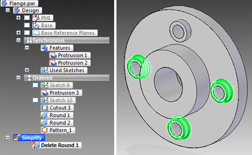
According to Deelip [Menezes, 2010], a new version of Solid Edge ST3 has a significantly modified feature tree. Now it consists of three parts: Ordered features, Synchronous features and Simplified view. The first part is typical for all systems that are based on the concept developed by Dr. Samuel Geisberg, first implemented in Pro/Engineer (and then repeated in CATIA, NX, Solid Edge, SolidWorks, Inventor and many other MCAD systems). It has usual parametric features (plain sketches and based upon them pads, holes, chamfers, fillets, pockets, etc.) They form a history-based ordered tree, which reflects their interdependence. Such features can be edited using special dialog forms (for instance, it is possible to change the type, diameter, depth and location of a hole). Professional MCAD users are well-aware of this.
Another part of Solid Edge tree has synchronous features, initially appeared in the first implementation of synchronous technology. They look like usual features but have an important advantage: these features can be changed by direct geometry editing, arbitrary mouse-dragging of 3D body faces and changing their form. This is how it looks for the users:
The third part of the Solid Edge tree (Simplify) contains simplified model representation, which enables to easily remove any face, region, hole or fillet from the model. This part bears no relation to the concept of dividing features into ordered and synchronous ones.
Conceptually, ordered (traditional) and synchronous features have a different nature. The former is a kind of a recipe, according to which the model is built (and re-built). The latter only group the body faces together. In fact, synchronous features amount to something more than simply face grouping.
In his blog, Deelip quotes Dan Staples [Staples, 2008], Solid Edge Development Director, who outlined a number of the key differences between synchronous and ordered features. In particular, synchronous features are not based on plain sketches. To be more precise, such elements like pads or holes certainly are sketch-based but later they can be parametrically modified without changing the initial sketch, which is fundamentally different from the traditional approach that requires modification of the original sketch to change the form of the pad/hole base. As there is no link with the sketch, synchronous features can be freely moved around the model and transferred to other faces, which certainly is one of the major advantages of this approach.
Synchronous technology enables users to regroup faces into new features (different from those by means of which they were created), allowing flexible editing unattainable in traditional history-based systems.
From the above it is clear that synchronous features are such sets of body faces, which enable automatic saving of geometric links between them. How did Siemens developers achieve this? I have a hypothesis described below in more detail.
Procedural and declarative features
Generally speaking, the idea of two feature representations is not new. Shah and Mäntylä [Shah&Mäntylä, 1995] described two approaches to representation of parametric features: procedural and declarative. Under the first approach, every feature is coded in a procedural language and combines definition of properties and its relations with other features with procedures for calculating these properties and relations. Under a declarative definition, features are described in a non-procedural language, where specification of relations is separate from their calculations. In the declarative approach properties and relations with other features can be given through rules or constraints.
In both cases features do not replace geometry but simply duplicate it at a higher level. Geometry is always created and supported within the geometric modeling framework (we know that Siemens uses Parasolid — one of the first commercial systems for geometric modeling based on boundary î geometry representation (BRep) developed by ShapeData in 1988), and features serve as a high-level interface between end-users and a geometric kernel.
In Solid Edge ST3 ordered features obviously represent the traditional procedural approach. Effectively, the ordered tree part is a geometry-building instruction: consecutive building procedure call for each tree feature in accordance with their order allows updating the model when parameters change. The situation with synchronous features is different.
I have reasons to suspect that Siemens synchronous features implement the declarative approach, when properties and relations with other features are given by geometric constraints (not transparent to the end-users), and calculation of properties and relations (for a modified feature) is done by solving a system of constraints (Siemens has the necessary technology - D-Cubed constraint solvers, connection of which with synchronous technology is mentioned in the company’s press-releases).
Shah and Mäntylä described the following areas for use of constraints in order to o set features:
- Inner-feature dependences,
- Composite dependences to set templates (for example, location of identical holes symmetrically along a circle),
- Dependences between component features, and
- Dependences between assembly components.
All constraints are classified as two groups — to set feature orientation (parallelism, perpendicularity, selected angle, coplanarity, coaxiality) and location (distance). Thus, Siemens synchronous feature is a set of geometric and dimensional constraints, non-transparent for end-users, that link the sub-set of body faces (geometrically representing a particular feature) between each other and to faces of other features.
What happens in course of direct face editing (mouse-dragging to a new location)? The procedure for dynamic constraint solving should be called to save the feature concept at each moment of time.
As declarative feature setting is based on non-procedural property description, properties can be transferred to an already existing geometry. Thus, the system can easily distinguish typical features (holes, chamfers, fillets) in a history-free model and represent them in the form of synchronous features for further parametric editing. Also it is possible to regroup the model features without re-building its geometry.
In LEDAS we have experienced firsthand how it is possible to successfully use geometric and dimensional constraints in parameterization of 3D bodies given in boundary representation. LEDAS has developed this approach as part of its variational direct modeling technology [Ushakov, 2008]. The idea is that the end-users work directly with geometry – bypassing the intermediate level in the form of features. In particular, our users can manually set any geometric or dimensional constraint between any faces, edges, and vertices of a boundary model. What is even more important that our technology can automatically recognize most of geometric constraints (parallelism, perpendicularity, coplanarity, coaxiality, tangency, equal distances and radii) and take them into account performing direct modeling operations. Those who wish, can download the latest beta-version of RhinoDirect plug-in to be certain how this concept is easy to use and how much time it can save for parametric modification of the model while preserving its design intent.
Let’s return to Solid Edge ST3.
How the two approaches can be combined within the same system?
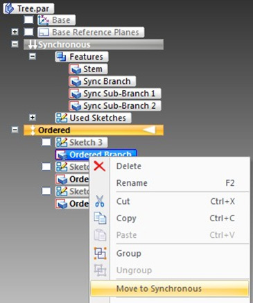
Solid Edge ST3 users are facing a choice: a feature can be created traditionally (the ordered method) or using synchronous technology. The choice is very important because in Solid Edge ST 3 features can be transferred from the ordered tree part to the synchronous tree part, but not vice versa.
Conceptually, there is nothing difficult in such a translation – simply the method to define a feature changes automatically: from the building procedure the system moves to a set of geometric and dimensional constraints on boundary elements. The problem is that a reverse operation is impossible: any feature of the ordered tree part has it place within the hierarchy - this is the nature of the procedural approach, while all synchronous features are equivalent, and apart from hierarchical they can also form cyclical dependencies (the latter, however, needs verification, which we are unable to complete due to absence of a necessary Solid Edge license in our hands).
BTW, direct transfer is not so simple and obvious for the users —subsequent to transferring features from the ordered part to the synchronous part, Solid Edge automatically transfers all parent features (on which the transferred feature is dependent). Indirectly it illustrates that in Solid Edge the synchronous part of the model is treated before the ordered part.
It implies yet another shortcoming of the current implementation of synchronous technology: when users create a new feature in the synchronous tree part, all ordered features temporarily disappear from the model! Understandably they are built on the synchronous part, which can change, but it is unclear, what prevents their presentation and automated recalculation at that moment. However, this shortcoming does not interfere with direct editing operations involving faces of synchronous features while working with the ordered part. In particular, it is possible to link parameters of features from two tree parts by formulae.
Dependencies between parameters
Formula dependencies are not a novelty in MCAD. True, one of advantages of parametric modeling is possibility to mutually define parameters. For instance, creating a pad it is possible to set that its height should be twice as high as the height of an earlier created pad. Such dependencies between parameters can be arbitrary complex and include not only arithmetic operations but also arbitrary functions (in particular, determined by users or external programs), and it is possible to use free variables, design tables, rules, etc. There is, however, one exception: parameters should not be cyclically dependent on each other. In particular, parameters of a feature located higher than another feature on the tree, cannot be directly or indirectly dependent on its parameters.
As in Solid Edge ST3 synchronous features are built before ordered features, the parameters of the latter can be linked by formula to the parameters of the former. Then, in particular, it will be possible to observe amazing effects of direct modeling, which in this case will change the form of ordered features after changing the synchronous features.
In LEDAS we believe that formula-based parametric modeling limits user expressiveness too much. Particularly, not all dependencies can be expressed explicitly: in the general case parameters can be linked by an implicit equation (for example, x^2+y^2=1) or even a system of equations. Furthermore, clear selection of a single output parameter in each formula forces users to completely modify specification moving from a direct task to the inverse one. In variational direct modeling, variables can be linked to each other by explicit and implicit equations. In this case there will be no requirement for absence of cyclical dependencies between parameters, and there will be no need to rewrite the equations when the set of input parameters is modified.
Conclusion
Let’s consider what exactly get users of Solid Edge with synchronous technology. On the one hand, Siemens developers have implemented a very powerful and simply-to-use declarative feature modeling (they call such features synchronous). Although the concept of constraint-based declarative features was suggested nearly twenty years ago [Balakrishnan, 1993; Ali, 1994], it is its first implementation in a popular commercial product.
Synchronous technology allows CAD users to operate in terms of traditional features, setting and editing them in a traditional manner. At the same time, it allows comprehensive direct geometry editing, transferring features to any model part, and not only within the same sketch plane; independence of each feature from early created features; and possibility to regroup faces in other types of features. It opens new capabilities for parametric modeling, mastering which users will be able to make changes to the models much faster.
On the other hand, an attempt to present two types of features in the same tree (procedural and declarative, or ordered and synchronous in the Siemens terms) looks like an unnecessary complication for the users. At a stroke, Siemens experts have made the tree twice as more complex, having non-trivial semantics of feature copying between its different parts (something can be copied, and something cannot; while some features will bring along other features, etc.) Perhaps, developers were driven by a desire to help users, accustomed to the history-based traditional approach, master a new synchronous technology. Perhaps, in Solid Edge sequels the ordered part of the tree will disappear forever because the only advantage of the history-based approach over the constraint-based one is how fast the model can be recalculated when parameters are changed. However, with advancement of the constraint solution methods and emerging of more and more productive computers this advantage is fading away leaving only drawbacks: impossibility to set cyclical dependencies between parameters, the need for repeated model design in the absence of the required parameter in the tree, insufficient means of direct model editing.
Synchronous technology is our future but why it has to come in the same package with an obsolete apparatus of history-based parametric modeling? These two approaches can hardly be combined due to significant conceptual differences, and as result a composed solution is controversial and unnatural for the users. Can it happen that Siemens disappoints its users with an excessive complexity of its combined solution? Would it be better to keep synchronous technology in its pure form – without linking to the traditional approach? We will not get the answers to these questions now, but Siemens solution has paved the way to other vendors who may prefer different strategies for launching s similar apparatus. That remains to be seen. In LEDAS we intend to be actively involved in the process.
References
- Ali, A., 1994, Declarative approach to form feature definition, M.S. thesis, Department of Mechnical Engineering, Arizona State University
- Balakrishnan, G.., 1993, Constraint based approach to product modeling, M.S. thesis, Department of Mechanical Engineering, Arizona State University
- Menezes, D., 2010, Synchronous Technology In Solid Edge ST3
- Shah, J. and Mäntylä, M., 1995, Parametric and feature-based CAD/CAM: concept, techniques, and applications. John Wiley & Sons, Inc.
- Staples, D., 2008, Explaining ‘Features’ To A Traditional CAD User
- Ushakov, D., 2008, Variational Direct Modeling: How to Keep Design Intent in History-Free CAD. LEDAS Ltd.
See also:
Permanent link :: http://isicad.net/articles.php?article_num=14064

|
 |