 |
Articles
10 Jun 2015 The CAD That Manufacturing NeedsDmitry Ushakov From the editors: This paper, based on the Russian original, was kindly edited by Ralph Grabowski who also published it, as a guest paper, in upFront.eZine e-newsletter.
 I read with great interest John Callen’s guest editorial about CAM [computer-aided manufacturing] and Onshape (upFront.eZine #856). Mr. Callen points out that CAD systems today still focus on defining geometry outside of a context that can actually manufacture its designs. I agree with Mr Callen that it’s a pity Onshape did not address the needs of manufacturing. And so I’d like to express my thoughts on the reason this situation exists, based on my experiences in collaborating with machine tool builders and CAM vendors.
Most modern CAD programs implement one of two approaches to 3D modeling: history-based and history-free, also called "direct modeling." The terms do not, unfortunately, reflect the underlying technology. There is one fundamental difference between the two, and it is the manner in which they change geometry:
- History-based changes force geometry regeneration by replaying the global design history
- Direct changes are done locally with no relation to the design history
History-based CAD systems dominated the CAD market since 1987, the time when Pro/ENGINEER pioneered the world of parametric design. More recently, most 3D CAD solutions were introduced or rewritten to exploit direct modeling. The list includes SpaceClaim, Synchronous Technology by Siemens PLM Software, Autodesk’s Fusion 360, and BricsCAD. But Onshape is history-based CAD. From the modeling point of view, it is just another Solidworks but one that flew out the Windows and into the clouds.
Nowadays, the border between the two classes of CAD has been eased. Some limited direct editing operations (like moving a face) can be recorded in a history tree, while parametric feature-based modeling can be implemented in history-free context. But the main problem inherent to history-based CAD still persists: history-based CAD cannot solve manufacturing tasks.
In this article, I describe the pros and cons of the solutions invented by the CAD industry:
- History-Based CAD
- Local Features in History-Free CAD
- Parametric Modeling in History-Free CAD
Through this discussion, I hope to show that much of the technology employed by many CAD systems rarely addresses the needs of manufacturing. First, a description of the CAD-created problem faced by manufacturing.
The Problem: Congenital Malformation
An inseparable property of history-based modeling is that it requires the model’s author to foresee all future modifications. I call this a “congenital malformation” -- the information needed at the birth of the model is unknown. If a later modification is not foreseen, then it is only possible to introduce it with a full or partial redesign of the model. This is the price paid by the users of history-based CAD systems and their parametric functions.
This has consequences for manufacturing. When finished 3D models are delivered to manufacturing, the engineers there typically need to modify the designs before they can be sent to the CNC [computer numerically controlled] machines. The only modifications that can be made are, however, those which were foreseen by the designers. Designers rarely understand manufacturing processes deeply, especially when manufacturing is outsourced.
Even if designers understand manufacturing, how can history-based CAD systems assist them? They can’t. As an example, let’s take sheet metal for CNC bending machines. In a simplified workflow, manufacturing receives the 3D models from the designers. The CNC operators unfold the models, order the bend operations, select specific bending tools for each bend, and then simulate the bending process in 3D: from the initial flat pattern to the final folded part. If a mistake is found, the part’s design has to be modified; for example, there might be a material conflict during bending.
Reworking the design is always possible; the same sheet metal part can be manufactured in many different ways. (See Figure 1.)
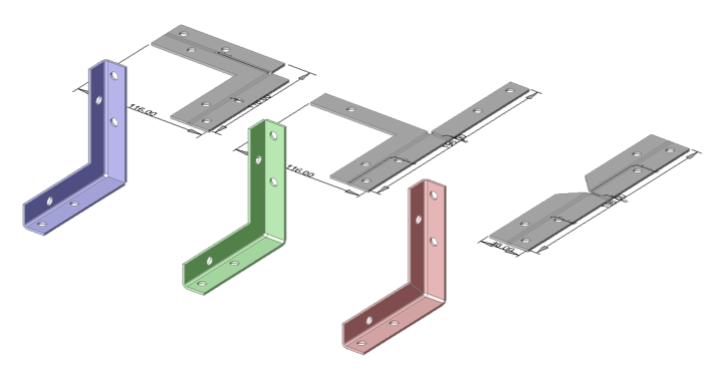
Figure 1. Different variants of the same sheet metal part
CNC operators need a way to switch between variants easily. Which modern CAD systems provide such tools? Let’s take a look at the technologies available.
A Solution: History-Based CAD
Onshape does not (yet) have a module for sheet metal design, so let’s look at the work by the same team in Solidworks. Sheet metal design was added in 1997, and then for the next twelve years the tools were limited to designing parts flange-by-flange. (Or, in even a more tricky way, by bending a planar part along a given line.) Perhaps that’s good enough for designers, but the only way to rework an existing sheet metal part created with this flange-by-flange approach is to redesign it from scratch.
More recent versions of Solidworks allow designers to convert 3D solid bodies into sheet metal parts. The decision whether to replace the initial body’s sharp edges with bends or rips is done at conversion time and then these instructions are stored in the history tree. This approach allows designers to switch between design variants of the same part by editing the corresponding “Convert to Sheet Metal” features in the tree. The flange-by-flange approach is, however, still the preferred way to design sheet metal parts, according to the help file in current releases of Solidworks.
But what about those sheet metal parts created in Solidworks 2008 and older? And what about sheet metal parts created in other CAD systems? The only way to rework them using history-based CAD is to design the parts from scratch. But there is a better solution than designing from scratch.
A Solution: Local Features in History-Free CAD
Feature-based modeling is a fundamental concept for design and manufacturing. It should not be associated with history-based CAD exclusively, because it can also be implemented on top of direct modelers. Here is how features are affected by the two types of modeling systems:
- History-based CAD. A feature is a parametric procedure. It is called to regenerate the model when a parameter is changed. History-based features form risky parent-child relationships, which have the ill of regeneration errors: when a parent feature is modified, its children cannot be regenerated if the geometry of their defining elements is changed or lost.
- History-free CAD. A feature is a group of faces (of a body) with associated behavior on movement, deformation, copying, and changing parameters. Direct modeling features are local; they do not form parent-child relationships. Any local feature can be deleted or transformed independently of the rest of the model; there is no risk of a regeneration error.
The direct modeling approach with local features allows designers and manufacturing engineers to switch between design variants easily, such as when they need to delete a feature, or want to replace a bend with a junction or rip. (See Figure 2.)

Figure 2. Switching between bends and junctions (rips) in a direct modeler
Another advantage to direct modeling is how easily it recognizes features in geometry that has been imported. Recognition of features is a straightforward process, which can be done invisibly to users. (History-based systems, by contrast, require the full design history to make imported geometry operable; reconstruction of design history usually requires manual work, because the same part can be designed in a “million” different ways.)
A Solution: Parametric Modeling in History-Free CAD
Manufacturing often makes the same parts in a variety of sizes. This is true also in the sheet metal industry, where for example industrial kitchen equipment is designed with a variety of sizes of cabinets, cooking units, and storage racks. The work of manufacturing is simplified when models can be reused for the same part but in different sizes. And this is possible with parametric design, which traditionally was the domain of history-based CAD.
But history-based parametric CAD suffers a major failing: we can only edit parametric models if (a) we use the same CAD system as the author of the model, and if (b) we have access to the design history. This is rarely the case in manufacturing, where models are sourced from many customers in a variety of CAD formats.
As it turns out, direct modeling CAD systems also can use parametrics. In this case, local features retain some degrees of freedom, rather than being fully constrained by history-based systems. For example, a flange is constrained only to the thickness of the sheet metal part it belongs to; its other dimensions are not constrained. This means that it is possible to do things like apply direct editing tools and to add dimensional constraints to control the size of the flange and specify relations between its features. In addition, direct modeling systems can add parametrics both to native and imported geometry.
My Conclusion
Of course, sheet metal design is just one example of the kinds of things that are manufactured from CAD models. Nevertheless, some observations can be made that apply to all areas of manufacturing:
Designers cannot foresee all model modifications required by manufacturing
Manufacturing engineers need complete freedom to modify models, and so cannot be limited to a particular design history
Manufacturing engineers use models produced by various CAD systems
Each of these observations is a serious argument against using history-based CAD systems in the manufacturing domain, and so explains why these CAD systems rarely address the needs of manufacturing engineers.
Dr. Dmitry Ushakov is ceo of Bricsys Technologies Russia, and has his PhD in Computer Science. He has 16 years experience in developing the underlying algorithms used by CAD software, and is the former ceo and cto of LEDAS.
See also:
Permanent link :: http://isicad.net/articles.php?article_num=17798

|
 |