 |
Articles
12 Oct 2008 
Variational Direct Modeling: How to Keep Design Intent in History-Free CADDmitry Ushakov Introduction
If creating new models or editing existing ones by using state-of-the-art 3D modeling programs (CAD) seem to be so complicated that you cannot master it in a couple of hours, perhaps it’s worth looking at the new design technologies. Even kids can clearly depict their thoughts and dreams in 2D pictures; however, not every adult can cope with transition to 3D images, especially technologies of history-based design, such as parametric feature-based modeling, which is standard for most “mechanical” CAD. To create a feature-based model is not so difficult; it is hard to control relations between features when changing the model. Editing the models created in a different CAD-system is even harder: there is no single standard for the features so some history data are inevitably lost in translation.
Both problems can be solved in an approach allowing direct (rather than history-based) manipulations with geometric model features. Still CAD-systems based on the above approach (direct, or explicit, or dynamic modeling) have not replaced history-based design. The reason is that by simplifying model editing operations such models leave too may degrees of freedom to the users. As a result, practically any editing operation unrecognizably changes the original model, “alienating” it from the design intent. A table is no more a table; a bearing is no more a bearing, etc.
How can smart geometric editing be combined with simplicity of user’s manipulations? The answer is in the new technology – variational direct modeling: using geometric and dimensional constraints to define the desired model behavior when modifying the model. Variational direct modeling simultaneously satisfies all constraints in contrast to the history-based consequence in parametric modeling. Variational modeling is possible due to use of modern symbolic and numerical methods of decomposition and solving large-scale geometric problems (including thousands of constraints). The set of constraints is a declarative construction to be interpreted uniformly regardless of their history. At the same time, constraints expressivities are sufficient to specify features and links between them. Constrains are set not only by a system user but also by the system itself which automatically identifies them building the original model or importing the model from another system. As a result, there is an easy-to-use tool to control feature concept of a product, which can adequately replace the current history-based and direct geometric modeling systems, combining their pluses and concealing their minuses.
This paper describes advantages of variational direct modeling applications for the end-users. Over a year ago LEDAS announced its plans to deliver ready-to-integrate toolkits of software components for developing variational CAD applications [1]. It is aimed at reducing the concept-to-delivery time and enhancing innovations by exploiting all advantages of variational modeling. One of the announced toolkits is designed for applying constraints to “dumb” (history-free) geometry. LEDAS is currently developing the toolkit, which will be available for licensing in the second quarter 2009. It is based on in-house variaional geometric solver LGS 3D, which can operate in combination with any geometric modeling kernel providing boundary representation (polygonal mesh or BRep). This solution enables bi-directional relations between geometric and parametric kernels: a user initiates changing of a geometric model according to the automatically identified or manually set geometric constraints and dimensions.
To demonstrate advantages of the new modeling technology to the end-users of the existing CAD-systems, LEDAS plans to release Driving Dimensions, a simple add-on applications to the most popular direct modeling systems that provide constraint-driven tools for geometry modification. The first in the series will be an application for one of the most sought-after direct modeling system – Google SketchUp. The paper outlines the plan for developing this application, which gives an idea of the high power of the new technology for any CAD-system.
Publishing this paper, LEDAS welcomes cooperation with all CAD developers and end-users.
Geometric Modeling from User’s Prospective
Creating 3D bodies in various CAD-systems looks the same. Using a set of 2D primitives, a designer creates a closed planar section, pulls it to construct a 3D body (prism), on the faces of which he (she) can construct other features that add or remove the volume. Each system has their own specific form features; profile-based features can be added 3D constructs – Boolean operations (such as intersection), mirroring, etc.
With similar approach to creating 3D form, CAD editing tools vary significantly. There are two classes of modelers: for history-based modeling, and for direct displacement of its boundary elements – faces, edges, vertices - by the users (called history-free or direct modeling). The first class is represented widely (becoming de facto industry standard for mechanical CAD), while the second class is so far represented by just a few systems (CoCreate, Kubotek KeyCreator, SpaceClaim, Google SketchUp, 3DVIA Shape). History-based form editing requires localization of an early modeling operation (feature) in the construction tree and editing its parameters. Changing parameters leads to automatic model reconstruction, including all modeling operations, which were subsequently recorded in the construction tree.
History-based editing has significant minuses: firstly, users spend time to localize the necessary operation in the construction tree (in simple cases a mouse click on the necessary feature in the 3D model would suffice but in more complex cases users must manually find the feature in the tree). Secondly, for complex constructions with hundreds features changing one of its parameters can trigger time-consuming model regeneration cycle, which significantly decreases user’s productivity. Thirdly, regeneration can change the body form in such a way that further modeling operations will be inapplicable (for instance, the hole exceeds the body boundaries) so users will have to manually change parameters of other features. Finally, history-based editing is not always practical. For instance, the history is almost always lost (fully or partially) in translating the file with the model from the format of a particular CAD-system to the format of another system (a model without history is called “dumb”). Even “smart” translators that can compare features of different systems or identify features in a “dumb” geometry do not solve the problem completely as different systems have different set of features.
Direct geometric modeling has none of the above shortcomings and prospectively is the master tool for editing 3D forms. Unfortunately, the existing implementations of direct editing in most CAD lack the key characteristic of the history-based parametric editing: possibility to introduce only those changes to the model that do not impair its integrity.
Let’s take the simplest example – a model of rectangular parallelepiped (box), see Fig.1(a). A history-based system knows that the parallelepiped was build by pulling a rectangle. A user can easily change the height of the box by editing the parameter of a relevant feature; to change its length and width users will have to go back to the parameters of its rectangular section. It is not completely transparent but any editing operation preserves the form – the hexagon will remain rectangular.
Direct editing of a box enables moving any face, edge or vertex. What will happen with the box if its vertex is moved by a user? Will the angles remain right? Will the opposite faces remain parallel? Will the faces remain planar? Will their number increase? Every direct modeling system gives different answers to these questions, which often do not match the user’s wishes. Let’s examine possible reactions of a modeler (see Fig. 1). Variant (b): only the moved vertex is displaced, others remain in place; but the system does not preserve even the number of faces and the form is lost. Variant (c): following user’s command, the system moves two more vertices, the model remains hexahedral, but parallelism and right angles of the faces are corrupted. Variant (d): the system moves three additional vertices preserving parallelism of the opposite faces and their linear dimensions. Finally, variant (e): the hexahedron remains rectangular, which is achieved by moving six additional vertices.
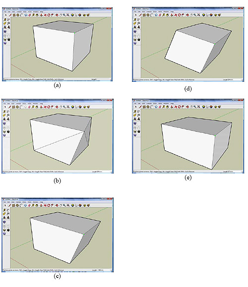
Fig.1. Behavior of direct modeler with vertex move
Why does it happen? How can users define the desired system behavior? Let’s analyze the situation from the developer’s prospective.
Geometric Modeling from Developer’s Prospective
The first CAD-systems used by aerospace and automotive enterprises from the mid-1960s, were 2D systems – an electronic version of a drawing board. Soon it became clear that design should be based on 3D product models, whose 2D projections can be generated automatically. However, simply adding a third coordinate to traditional 2D graphics results in modeling only a wireframe, which is not sufficient for calculating mass/volume characteristics of a future product. Only solid modeling allows describing each point of the body and paves the way to other methods of engineering analysis of static and dynamic properties of the product. Furthermore, a solid-body model is used for calculating the cutter trajectory in CNC product manufacturing, as well as for rapid prototyping. Thus, solid modeling forms the basis of CAD, CAE and CAM systems.
Majority of the modern geometric modeling kernels are based on the same solid modeling apparatus – boundary representation (BRep), which describes the body by listing volume-constraining planar and curvilinear faces, that cross in edges and vertices (all called boundary elements). Incidence between boundary elements defines the topology of a model, while their parametric properties define its geometry. Such representation enables easy calculation of mass/volume characteristics of the body and modeling Boolean operations (intersection, union, difference).
Form features (originally adopted from Computer-Aided Process Planning systems) can also be modeled by boundary representation. From the designer’s prospective, a form feature is a geometric image of an elementary operation of a metal-cutter, such as drilling, turning, milling. The idea to integrate product design with process planning was popular in the 1980s, when pilot projects were implemented by several research laboratories in different countries. Pro/ENGINEER, released in 1987, became the first commercial feature-based CAD system.
It set the industry standard for the next 20 years: nearly all modern CAD implement features on the basis of the so-called procedural approach [2]. Under this approach, every type of features is related to a group of methods for creating, deleting, updating, editing and copying such types of features. Under the procedural approach, parameters required for geometric construction of a feature (for example, axis, diameter and depth of a hole) can be divided between dependent and independent. For instance, the hole axis is typically parallel to the normal surface of the face, where a relevant feature is build; so if the orientation of the face is changed, the hole axis also must be changed. The hole diameter, however, is an independent parameter, set by a user during modeling, and does not depend on other features (if only it has not been equated to a diameter of another hole). The procedural approach forces developers to abandon cyclic dependencies between features because the model update cycle can otherwise be infinite if a parameter is changed. This user’s paradigm is called parametric feature-based design.
Another long-known way to features modeling is the declarative approach [2]. Each feature is given by spatial relations between boundary entities that specify its geometric form. For instance, in a prism formed by pulling a planar section, normals of geometric surfaces of all its side edges are perpendicular to the surface normal of constructing the section. Similarly, all cylindrical edges of a hole feature are coaxial and the direction of a common axis is parallel to the plane normal of the face where the bore was constructed. Such spatial relations are geometric constraints. To satisfy these constraints in direct geometric editing (for instance, displacing boundary elements), the system of simultaneous constraints should be dynamically solved.
Geometric model with constraints is called variational (traditionally, the term is used as opposed to parametric model, which in users’ and developers’ mind is inseparably associated with the history-based modeling) and has been long the focus of developers’ attention. Currently there are several commercial variational geometric solvers on the market of software components, that can effectively solve the systems with thousands simultaneous constraints. Until recently they were only used for solving 2D constraints in variational sketching as well as implementing top-down assembly design (where the parts are linked with assembly constraints, whose simultaneous solving determines the assembled mechanism).
LEDAS realized the prospects of using variational geometric solver in direct geometric modeling a year ago [1]. Six months later Siemens PLM Software, a leading CAD developer, announced developing synchronous technology [3] – history-free model editing that preserves features. According to the advertising materials of the developing company, synchronized technology is a kind of declarative approach to features modeling by setting geometric and dimensional constraints between boundary model elements. Such a technology combines the functions of the Parasolid geometrical modeling kernel and the DCM variational geometric solver.
Below we present out opinion of variational modeling in the context of direct geometric editing, in continuation of our ideas published a year ago [1].
Variational Direct Modeling
Let’s get back to the question raised at the end of the first section (Geometric Modeling from User’s Prospective) – how can users set the desired model behavior for its future modifications? The most natural method of such specifications is by geometric constraints and dimensions. Possibility to relate faces, edges and vertices by constraints of coincidence, parallelism, perpendicularity, tangency, ńoaxiality, symmetry as well as setting dimensional constraints (radius, length, distance, angle) gives the users of a direct modeling system a simple but powerful tool for specifying future behavior of the model in course of its editing. This is a method of specifying design intent – essentially, similar to history-based parametric design, but much more powerful and flexible.
However, it would be wrong to burden users with complete manual specification of the desired behavior. Many design intents can be identified automatically. First, many model editing operations (such as displacing faces, edges or vertices) assume that model topology (that is, coincidence of its boundary elements) remains unchanged. In variational model, coincidence of a face with its edges requires the corresponding geometric constraints between relevant geometric objects – surfaces, curves and points. The system can automatically generate such constraints according to topological data structures of a BRep-model. If we ignore them, most editing operations become incorrect (see Fig.2).
Fig.2. Topology breakdown
Second, when a user is constructing the model using various features, the system can automatically add the above-described geometric constraints matching the features (perpendicularity of a prism side faces to its section plane, coaxiality of the hole elements, etc.)
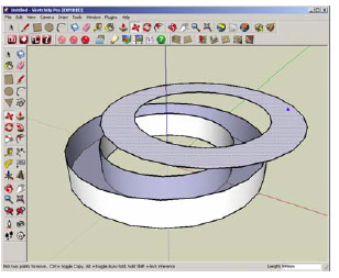
Third, geometric constraints can be identified even under the “dumb” geometry (without history). For example, constraints of face coincidence, parallelism, perpendicularity, coaxiality, concentricity and tangency can be constructed upon the original position of faces in a BRep-model. A set of non-contradictory geometric constraints between boundary elements of “dumb” geometry can be generated by non-complicated rules, whose pattern can be given by a user. Fig. 3 demonstrates the behavior of direct editing an initial cylindrical part (a) with no coaxility constraint (b) and when they are automatically recognized and generated (c).
Fig.3. Direct editing a cylindrical part
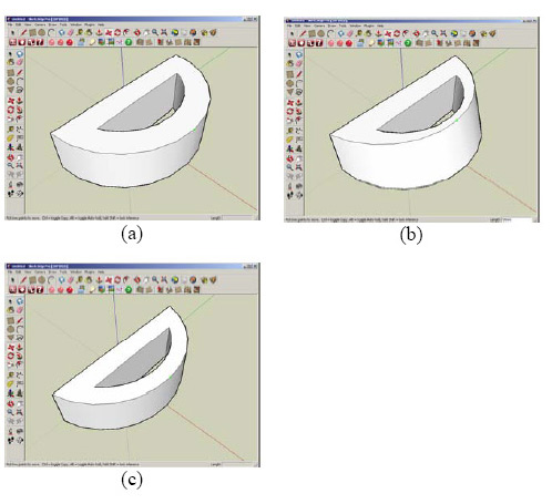
Table 1 sums up possible constraints in variational direct modeling.
| Source of constraints |
Types of constraints |
| BRep Topology |
Coincidence of surfaces (planes), curves (lines) and points |
| BRep Geometry |
Coincidence, parallelism, perpendicularity of lines and planes, coaxiality/ concentricity of cylinders, spheres, cones and tori, contingence, symmetry |
| Features |
Parallelism of axes, coaxiality/ concentricity of cylinders, spheres, cones and tori |
| User |
Any geometric constraints (including absolute and relative fixation) and dimensions |
Table 1. Direct Modeling Constraints
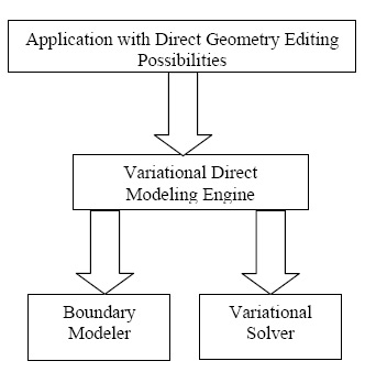
The Table specified the sources of information, which is in the model (history-based or history-free geometry) and which can be put in the form of geometric constraints and dimensions. Combining BRep modeler with variational geometric solver allows implementing this approach in any direct modeling system. In the near future, LEDAS, in line with the announced course for developing ready-to-integrate toolkits as the basis for end-user applications with variational functionalitites, plans to release the toolkit for direct geometric modeling based on LEDAS variational geometric solver LGS 3D. Open toolkit architecture (Fig. 4) facilitates integration in any system of geometric modeling on the basis of boundary representation (polygonal mesh or BRep).
Fig.4. Architecture of a variational direct modeler
To demonstrate expressive capabilities of the toolkit, LEDAS has developed an add-on application for one of the most popular systems of direct modeling - Google SketchUp.
Driving Dimensions for SketchUp
The concept of driving dimensions is well-known to the users of numerous systems based on variational approach. Unlike ordinary (reference) dimensions (radius/diameter, length, distance, angle), calculated according to a geometrical model, driving dimensions augment automatic changing of the position of model features in accordance with the specified distances and angles.
A popular direct modeling system Google SketchUp [4] is familiar to not only professionals in architecture, engineering and construction design but also many amateurs that create virtual 3D worlds (created models of real objects can be linked to a certain area by placing them in the Google Earth geoinformation system). With accessible direct modeling capabilities, SketchUp limits user’s capacity of model parameterization. Effectively, dimensions can be set only at the time of constructing the model. It is impossible to edit the model by changing dimensions and users can apply only the simplest scaling functions. To make variational design tools accessible to a wide range of SketchUp users, LEDAS has developed an add-on application for this system called Driving Dimensions. It can define dimensional constraints between model features (faces, edges and vertices).
Application with Direct Geometry Editing Possibilities
In the first version of Driving Dimensions (which will be available for testing free-of-charge in October 2008) user will already be able to set the length of an edge and the radius of a circle or an arc. With simultaneous solving of all dimensional constraints (preserving the topology of the original model - the number and incidence of its elements) users can easily exercise parametric modification of any model, created independently or found in the vast database of free models - 3D Warehouse [5]. In the follow-up versions of the application (which will be released later in 2008 and 2009), users will be able to define any dimensional and geometric constraints, using the tools for automatic generation of constraints, when model elements are created, and according to geometric properties of “dumb” geometry. Apart from static satisfaction of constraints (when setting a constraint or following a special user’s command), there will be possibility of dynamic satisfaction of constraints when moving any number of model elements.
Since the basic versions Google SketchUp and Driving Dimensions are free, everybody can appreciate the main advantages of variational direct modeling:
- Using geometric and dimensional constraints in design considerably reduce the model-creating time.
- Adding design intent in the form of constraints between the model elements and saving them in the file together with the model simplifies future editing.
- Using constrains for editing a foreign model without constraints rapidly adapts the existing models for the new tasks.
Fig.5 shows a simple model successfully parameterized using Driving Dimensions.
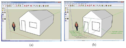
Fig.5. Model of a house before (ŕ) and after (b) parameterization
Conclusion
Variational direct modeling combines smart parametric approach with flexibility and simplicity of direct geometry editing.
LEDAS announces development of a toolkit for implementing relevant functionalities, which will be available to CAD developers for licensing in the second quarter 2009.
End-user capabilities of variational direct modeling will be available to all interested persons in October 2008 as part of an add-on application Driving Dimensions for the popular 3D design system Google SketchUp. LEDAS intends to further develop functionalities of this application and release similar applications for other well-known CAD-systems.
References
- Dmitry Ushakov. Using LEDAS Computational Software Toolkits to Shorten Development Cycle of Variational CAD Systems. August 2007, LEDAS Ltd. URL: http://www.ledas.com/group/white_papers
- Jami J. Shah and Martti Mäntylä. Parametric and Feature-Based CAD/CAM: Concepts, Techniques, and Applications. Wiley, Chichester, 1995, 619 pp.
- Synchronous Technology. April 2008, CPDA LLC.
- Google SketchUp. URL: http://sketchup.google.com
- 3D Warehouse. URL: http://sketchup.google.com/3dwarehouse
About the Author
Dr. Dmitry Ushakov, Director, Product Management & Marketing, LEDAS Ltd.
Dr. Ushakov has 15 years of experience in computational software development with different applications to CAD domain. In 2001-2008 he took the position of Chief Technology Officer at LEDAS Ltd. He coordinated software development projects aimed at creation of constraint solvers for geometric and engineering problems. In 1999-2001 Dmitry was temporarily assigned to Dassault Systemes, where he was working on development of a core mathematical solver and end-user components of CATIA V5 system for knowledge-based engineering.
Prior joining to LEDAS, Dr. Ushakov was a scientist at the Russian Research Institute for Artificial Intelligence. His interests were in the area of theoretical foundation of constraint programming and development of computational software for solving a broad range of constraint satisfaction problems in various domains.
Dmitry graduated from the Novosibirsk State University in 1993 with specialization in mathematics and applied mathematics. In 1995, he received the degree of Master of Mathematics, and in 1998 received a PhD degree in Computer Science at the same university.
Dr. Ushakov is the author of more than 50 scientific papers.
About LEDAS
LEDAS Ltd. is an independent software company founded in 1999; it is based in Novosibirsk Scientific Centre (Akademgorodok), Siberian Branch of the Russian Academy of Science. A leader in constraint-based technologies, LEDAS is a well-known provider of PLM components: geometric constraint solvers for CAD/CAM/CAE, optimization engines for Project Management, Work Scheduling and Meeting Planning as well as interval technologies for Knowledge-Based Engineering and Collaborative Design.
The company also provides services for PLM and ERP markets: software development, consulting, reselling as well as education and training. Detailed information about LEDAS is available on the Internet at: www.ledas.com
Permanent link :: http://isicad.net/articles.php?article_num=12886

|
 |