|
Articles
14 Nov 2011 Direct Modeling - Who and Why Needs It? A Review of Competitive TechnologiesDmitry Ushakov This review is based on the author’s invited talks at the Autodesk Forum and Bricsys International Conference that took place in September – October 2011 in Moscow and Brussels. Russian version of this paper is available here.
When in 1985 Samuel Geisberg, an émigré from the USSR and a former professor of Leningrad University, founded Parametric Technology Corporation (PTC) in the USA to develop a Pro/Engineer system that revolutionized the market of MCAD (mechanical computer-aided design software), could he imagine that parametric feature-based modeling, taken as its basis, would dominate the industry for a quarter of the century and that all leading MCADsystems (CATIA and NX, as well as Windows generation represented by SolidWorks, Inventor and Solid Edge) would become ideological successors of Pro/Engineer? And could he guess that having achieved an incredible commercial success, PTC would unexpectedly for everyone make a decision to sacrifice the holy of holies – the Pro/Engineer brand?
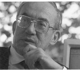
Pic. 1. Samuel Geisberg, the founder of PTC, the “father” of Pro/Engineer and the inventor of parametric modeling based on feature history.
Analysts have reasons to believe that this decision of PTC is directly related to the recent (2007) acquisition of CoCreate that pioneered an alternative approach – direct modeling. The new brand (Creo) and new applications sharing the same data format (Creo Parametric and Creo Direct) reflect how PTC sees the modern state of the MCAD market – now it does not have a dominant technology, so the “bronzed” brand (Pro/Engineer) is no longer required.
Naming its new applications, PTC emphasises that there are two approaches to solid modeling – parametric and direct, and each has its own niche. It seems that developing the second approach was a clear credit for CoCreate.
CoCreate – the Pioneer of Direct Modeling
Few heard about CoCreate before PTC bought it for 250 million dollars four years ago. At that time CoCreate had 280 employees and served the needs of 5000 customers (including such dominant names as Fujitsu, HP, Liebherr, NEC, Panasonic, Epson) earning $80 million annual revenue. In spite of rather modest figures, CoCreate had a glorious track record under its belt, rooted in the Mechanical Design Division of Hewlett-Packard. It was this Division that in 1992 developed a novel 3D modeling system - SolidDesigner. Unlike other well-known MCAD systems of that time, SolidDesigner was based on dynamic modeling – as an alternative to history-based modeling.
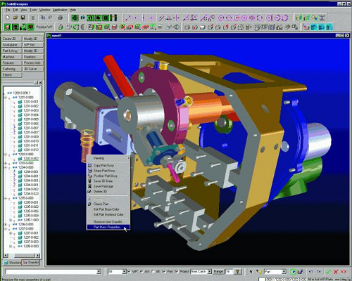
Pic. 2. HP Precision Engineering SolidDesigner – the pioneer on direct modeling for MCAD.
Here I have to digress a little bit from the main subject in order to clarify terminology because in the text above I’ve already managed to use four different terms related to solid modeling: parametric modeling, direct modeling, dynamic modeling and history-based modeling. Thinking logically, parametric model is a geometric model with parameters that can be changed to get different design variants. Parametric modeling is a fundamental CAD concept that significantly cuts down the costs of introducing changes to the project, creating new modifications, etc.
However, since initially parametric models were based on design history, a rather stable link appeared between those completely different concepts. True, design history (the record of operations used to construct a geometric body shape from scratch) can easily be transformed into a parametric model, if a set of parameters is associated with each operation. Examples of such parameters are types and coordinates of two-dimensional entities of a 2D profile and the height of its extrusion in 3D space, or the diameter and depth of a hole. Changing their values and regenerating the design history, a different variant of the same geometry can be created. Parametric features used by Samuel Geisberg in Pro/Engineer formed a tree that was automatically built according to the design history. Later this method was copied in practically all MCAD systems.
With all simplicity and universality, this history-based parameterization method has some serious drawbacks. The most important are its complexity and lack of transparency for the customers. To change a geometric shape, one must locate a proper feature in the tree and figure out, which specific parameter should be changed. The fundamental principle of a user’s interface - WYSIWYG (What You See Is What You Get) - does not work here because you edit a text or a numerical value of a feature parameter, and as a result change the geometric body shape.
It is well known that in large geometry models design history can be rather long and its regeneration can take much time, which puts MCAD users in a pending position and force them to waste their time and nerves in vain.
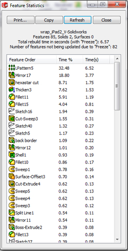
Pic. 3. Slow regeneration of a history tree in SolidWorks forces users to “freeze” regeneration of certain features – in order to accelerate the overall process.
Another notorious drawback of history-based parameterization is that a decision, which model parameters can be changed, must be taken when you create the model. If later for some reason you need to change a particular parameter that in absent in the tree, the solution will not be easy: either to redo the model from scratch or use complex optimization algorithms in an attempt to approach the desired value of the parameter in question by varying the values of the defining parameters (which are presented in the tree).
This shortcoming reflects the overall problem of a procedural approach to parameterization, a kind of which is the method of history regeneration. Under a procedural approach you in advance divide all model parameters into the input and output ones. It is only possible to change parameters of the first group, while the values of output parameters are calculated in accordance with pre-determined procedures, formulas, history, etc.
Finally, another key problem of history-based parameterization is inability to use this technology when working with multi-CAD and legacy data. Design history is typically lost in translation from one CAD format into another. Only boundary model is translated, which in this case is called “dumb” geometry. Some expensive translators can convert features from one system into another, but it’s not a panacea as each system has its own mix of features and exact translation is impossible in principle. The same can be said about automated feature recognition in “dumb” geometry: it can work only in the simplest cases and does not resolve the general problem.
All above-mentioned flaws of history-based parameterization were successfully overcame in a dynamic modeling system - SolidDesigner, which for the first time equipped users with the tools for direct manipulation of elements of a geometric model in 3D space. It became possible, first of all, due to ACIS – a solid modeling kernel that HP was the first to license from Spatial in 1989.
ACIS models solid geometry by boundary representation (BRep) and implements Boolean operations on solid bodies (that form the basis for form features). Boolean operations are global in the sense that union, intersection or difference of two bodies require compute-intensive operations with their complete boundary structures (here lies the productivity problem of history-based parametric systems). Spatial, however, also implemented the so-called local operations in ACIS; to perform them it suffices to work with some local neighbourhood of the body boundary. In many cases local operations do not require changing the model topology (the number of its faces, edges, vertices, and the adjacency between them), and, therefore, can be performed quite efficiently. For more details please see the “HP PE/SolidDesigner: Dynamic Modeling for Three-Dimensional Computer-Aided Design” published in the October issue of the corporate journal of Hewlett-Packard in 1995.
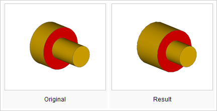
Pic. 4. Local operations in ACIS form the basis for efficient direct modeling.
Dynamic modeling by HP enabled users to chose one or several faces in a model and translate or rotate them. SolidDesigner helped users automate selection of adjacent faces that form a feature (a pocket, a fillet, a hole, etc.) SolidDesigner also allowed copying a feature from one place to another.
Parametric editing was performed with the help of so-called driving values. Users could set one or several 3D labels in the model to specify the required distances and angles between the faces, and the system would automatically perform the relevant local operations to satisfy them in turn, step-by-step. An iterative solver was not used for these operations.
In 1996, under the pressure from its customers, many of whom were developing their own MCAD systems, HP spun the Mechanical Design Division off into a child company called CoCreate and in 2000 sold it to investment funds. Seven years later CoCreate found itself under control of PTC (a direct successor of SolidDesigner is now known as Creo Elements/Direct, and its underlying ideas are implemented in a new product - Creo Direct, which, along with Creo Parametric, is none other than a reincarnation of “lying-in-state” Pro/Engineer).
The approach proposed by CoCreate got the name of “direct modeling” (the term “dynamic modeling” did not make good). Direct modeling allows modifying 3D geometry regardless of its history. One should not confuse methods of geometry modeling (with or without a tree) and the editing methods, as rightly pointed out by Paul Hamilton in a series of publications “Editing 3D Geometry” (Hamilton worked for Hewlett-Packard since 1977 and then moved with other co-workers to CoCreate, and later to PTC).
Direct editing is a process of translating / rotating / copying / removing one or several body faces (for instance, ones forming a particular form feature). Editing parameters of features or driving dimensions is therefore called indirect editing. Direct editing is typical for direct modeling systems, while indirect editing is present in the history-based systems. However, SolidDesigner had both types of editing. Developers of IRONCAD for the first time showed direct editing within history-based modeling. Nevertheless, the market did not notice all these achievements up to a certain time.
Rediscovery of Direct Modeling
Everything changed in 2007 when PTC announced its deal with CoCreate, and the first version of SpaceClaim - an absolutely new direct modeling system - was released by the same-name company, created by Blake Courter and David Taylor, former employees of PTC. SpaceClaim made its stakes on the market when an industry legend Mike Payne was appointed its CEO. A co-founder of PTC and SolidWorks, he helped the new company to attract serious investors and build a solid customer portfolio. A real success was signing OEM agreements with TRUMPF, the world's largest manufacturer of metal-cutting machines, and ANSYS, a leading provider of computer-aided engineering (CAE) solutions. Thus, SpaceClaim clearly outlines two niches where direct modeling can bring significant benefits: preparing geometric models for CAM (computer-aided manufacturing) and CAE. Conceptual design turned out to be the third niche.
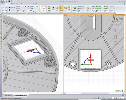
Pic. 5. SpaceClaim – a catalyst of modern direct modeling mania.
In principle, SpaceClaim did not offer anything new that SolidDesigner did not have: the same kernel (ACIS), the same concept of “smart” multi-selection of body faces, and the same direct and indirect editing operations. However, being designed from scratch for the Windows platform it looked very modern unlike CoCreate, and generated by far more marketing noise: each year SpaceClaim reported threefold increase of their customer base (however, without disclosing absolute figures).
So the big vendors reeled back. A year later Siemens PLM Software announced its synchronous technology (admitting that it had been under development even at the times when the company was named Unigraphics); in 2009 Dassault Systemes presented CATIA V6 LiveShape to the world; and Autodesk – its Inventor Fusion technology preview. These were applications for direct modeling, with the format compatible with the history-based systems from the same vendors.
As nobody really saw LiveShape (there is no single thorough review of the capabilities of that application in the Internet), I am going to discuss only Siemens and Autodesk approaches. But to start with, I’d like to remind of my own approach called variational direct modeling, which I outlined for the first time in 2007 in my paper “Using LEDAS Computational Software Toolkits to Shorten Development Cycle of Variational CAD Systems
” and in 2008 described it in more detail in the paper “Variational Direct Modeling: How to Keep Design Intent in History-Free CAD”. I’d like to remind about that because both approaches later proposed by Autodesk and Siemens conceptually have much in common with variational direct modeling.
Variational Direct Modeling
When I talked about the shortcomings of a procedural approach to parameterization (the main one is a priori split of all parameters into input and output ones), I did not mention a long-known alternative – variational modeling. In variational modeling parametric connections of a model are set declaratively – by listing the constraints connecting the model's elements. Unlike procedures, formulas and design history, constraints are not oriented: they do not determine which of the connected parameters is an input or an output one. Therefore, constraints can easily form cyclic dependancies between parameters (for instance, x=2*y and y=x-2), so a special iterative solver is required that can resolve all given constraints simultaneously by calculating new values for all linked parameters.
Such solvers are well-known. Some of the first commercial products were the 2D/3D DCM solvers developed by a UK-based company D-Cubed (currently a part of Siemens PLM Software) starting from the end of 1980s. Now they compete on the market with LGS 2D/3D developed by a Russian company LEDAS since 2001 and recently under a new ownership – Bricsys (Belgium). Traditional areas for application of such solvers used to be 2D parametric drawing/sketching and 3D assembly design/kinematics. However, in combination with an efficient solid modeling kernel, variational solvers can also be applied to control the shape of solid body geometry represented as BRep. It is for this application area that I’ve suggested to use the term “variational direct modeling”.
In 2008 LEDAS released its first product for variational direct modeling with limited capabilities for Google SketchUp; in 2009 started a more advanced product for Rhino (the first commercial version of the plug-in - RhinoWorks - was released in April 2011); and in 2010-2011 signed contracts for developing similar functionality in Bricscad and KOMPAS-3D. Today the most efficient implementation of variational direct modeling technology is in Bricscad, with a great credit due to ACIS – the kernel that formed the basis of SolidDesigner and SpaceClaim.
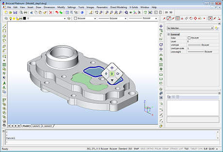
Pic 6. Variational direct modeling in Bricscad V12.
An important part of the developed technology is a possibility to avoid manual specification of a great number of constraints that would guarantee keeping the design intent of the model. In direct modeling systems this intent can easily be lost. For instance, if you attempt to edit a 3D model of a table by rotating the upper face of its top (to incline the table top to the floor level), in all likelihood you’ll be annoyingly surprised with the results. To get a correct modification of such a model it is necessary to simultaneously rotate not only the upper but also the lower and side faces of the table top to keep their mutual parallelism and perpendicularity accordingly. In SolidDesigner and SpaceClaim such functionality is achieved by using patterns, enabling to select several facets simultaneously. However, multi-selection for complex models can be inefficient and has a much reduced capacity - in comparison with automatic constraint recognition.
Variational direct modeling is a combination of the best of the two worlds: history-based parametric modeling and “pure” direct modeling as you can see in the Table below:
| |
History-based |
“Pure” direct modeling |
Variational direct modeling |
| Easy to learn and use |
No |
Yes |
Yes |
| WYSIWYG mode |
No |
Yes |
Yes |
| System response time when changes occur |
Slow |
Fast |
Fast |
| Possibility to specify design intent |
Yes (features) |
No |
Yes (constraints) |
| Automatic recognition of design intent |
Limited to simplest features |
No |
Full |
| Direct editing |
Limited |
Full |
Full, keeping design intent |
| Parametric editing |
Limited by history tree |
Elementary (step by step) |
Full |
| Editing imported geometry |
Impossible |
Possible |
Possible |
Synchronous Technology
What Siemens PLM Software revealed to the world as synchronous technology, in fact was known to the experts before. In their book “Parametric and Feature-Based CAD/CAM” Jami Shah and Martti Mäntylä described two approaches to defining features – procedural and declarative. In the procedural approach generic features are predefined in terms of a collection of related procedures, i.e. methods for instancing, modifying, copying, and deleting features, generating feature geometry, deriving certain parameters, and validating feature operations. The essential characteristic of the declarative approach is that the system uses a non-procedural method to describe features and their properties.
Declarative methods separate feature definition from the implementation. This is in contrast to the procedural approach, where the two are interwined in the procedure definition. To achieve the separation, the geometry and other properties of features can be defined in terms of relationships (constraints) between boundary-based modeling entities (faces, edges, vertices). This leads to a so-called constraint-based feature definition.
For instance, an “extruded profile” can be defined by perpendicularity constraints between the profile plane and side faces formed as a result of its extrusion, as well as by the distance constraint between the profile plane and the top (extruded) face. Such constraint-based feature definition enables direct editing of a model – transforming body faces under constraints. In this case each transformation is done dynamically, while simultaneously satisfying all constraints that define the model. As a result, after each transformation constraints remain satisfied, which means features still correspond to their definition (and design intent of the model is kept).
Combining capabilities of Parasolid geometric modeling kernel and 3D DCM geometric constraints solver, engineers of Siemens PLM Software implemented the so-called synchronous (declaratively defined by constraints) features in Solid Edge, providing their users a choice: either immediately design their models using synchronous features or build hybrid models with a tree comprising both procedural (ordered in the Siemens terminology) and new synchronous features (see “Synchronous Technology: the Third Attempt”).
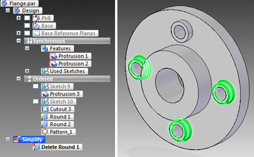
Pic. 7. Synchronous technology in Solid Edge.
Combining Direct Modeling with a History Tree
Autodesk and PTC have offered their users a different approach, where direct geometry modeling takes place in separate applications (Inventor Fusion and Creo Direct accordingly), and users perform direct and indirect model editing (by means of driving dimensions) having no access to the design tree. Then the same model can be downloaded in a “classic” history-based application (Inventor and Creo Parametric), where the changes made to the model in a direct modeling system can be integrated in its design tree.
Here PTC uses a rather straight approach, writing up pseudo-features like Move and EditRound to the end to the design tree (see “Creo Explained - Part 5” by Deelip Menezes), while Autodesk has implemented a dedicated Change Manager that is able to translate direct editing operations into operations of changing parameters of the features already presented in the design tree.
Interestingly, in Inventor Fusion (as well as in its re-branded version for DIY market called Autodesk 123D), Autodesk has also implemented a very simple constraint solver, which made these applications slightly similar to those being developed by LEDAS, except that Autodesk products do not have an automatic constraint recognition module and the set of possible constraints (including all variations of types of their parameters) is considerably poorer. Nevertheless, there are no doubts that this functionality will be built up as new versions are released.
Editing Imported Geometry
Siemens, Autodesk and PTC approaches are aimed, first of all, at giving users of their classical MCAD applications a possibility to use direct modeling. Being probably truly alarmed with SpaceClaim efforts and an overblown fuss around it, these reputable vendors primarily have been resolving the task of preserving their own customer bases. Effectively they have told their users: “You wanted direct modeling? You’ve got it! Now you can promptly, conveniently and demonstrably (no worse than in SpaceClaim) edit your own models and even integrate your changes into design history (impossible with SpaceClaim)”.
Let’s return to yet another problem of history-based modeling, mentioned at the beginning of the paper: work with multi-CAD and legacy data. The importance of work with such data is beyond doubt: according to a recent survey conducted by Aberdeen Research, 82% of the respondents who work at design divisions use three and more CAD data formats, and 42% - more than five formats. The reasons are quite objective: the essentiality of close cooperation with OEM vendors, long life cycles of designed products (exceeding software life cycles), historical factors influencing business development.
Respondents stated that the major problem of work with multi-CAD data is losing intelligence embedded in the original model within the system where it was created. In an “alien” system the design history is lost, and parametric geometric model become “dumb”.
Direct modeling systems can be used to change a “dumb” geometry”, but they cannot keep the design intent of the initial geometry. Variational direct modeling technology answers this issue, because it can automatically recognize design intent of a “dumb” geometry” in terms of geometric and dimensional constraints between boundary elements. If two planar faces of a model are parallel or perpendicular to each other, such orientation is most likely was intended by a designer of the initial model. So very probably these faces should remain parallel (perpendicular) when the “dumb” geometry is edited by the user (except when the user explicitly specifies a different angle between the two faces). The same is true for holes of equal diameter, pockets of equal depth, various types of model symmetry, etc. All such relationships can be recognized and used for modification of the “dumb” geometry.
Constraint recognition is by far easier that feature recognition or tree reconstruction, because it is easy to verify possible geometric relations by iterating boundary elements. It is precisely what I see as the key to the intelligence of direct modeling systems. Certainly, a possibility to add user specifications to the “dumb” geometry (whether that be constraint-based feature definitions or just unit constraints) allows to express its design intent in the most powerful way.
Direct Modeling Challenges
The weak spot of all modern direct modeling systems remains editing complex NURBS surfaces. Recognising planar, cylindric, spheric, conic, or toric faces in a boundary model is one thing. And another is to recognize that a particular face is a result of sweep, loft, or blend operations. Such recognition is absolutely needed to edit these faces according to their design intent. And I don't know any direct modeling system that is able to edit (directly or indirectly) such shapes as springs, propellers, wings, cowlings, etc.
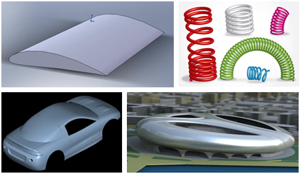
Pic. 8. Editing complex NURBS surfaces is a challenge for modern direct modeling systems.
Technology is forging ahead. I am convinced that soon we’ll see how direct modeling systems will boldly “crack” standard machine-building components with such complex faces. For now, however, if you design products with non-trivial geometry, it is better to apply history-based systems.
In many other cases a direct modeling system can be the only right choice. You have to work with multi-CAD and legacy data? You cannot invest in training of your specialists (it is anything but easy to learn the correct methods of history-based modeling)? Or you don’t have the funds to buy an expensive license (“classic” MCAD systems are far from being cheap)? Then you should consider a possibility to use one of direct modeling systems described in this review.
Please send your feedback on the paper to info@isicad.net.
References
- Klaus-Peter Fahlbusch and Thomas D. Roser, “HP PE/SolidDesigner: Dynamic Modeling for Three-Dimensional Computer-Aided Design”, October 1995 Hewlett-Packard Journal.
- Jami J. Shah and Martti Mäntylä, “Parametric and Feature-Based CAD/CAM”, John Wiley & Sons, Inc., 1995.
- Dmitry Ushakov, “Using LEDAS Computational Software Toolkits to Shorten Development Cycle of Variational CAD Systems
”, 2007.
- Dmitry Ushakov, “Variational Direct Modeling: How to Keep Design Intent in History-Free CAD”, 2008.
- Paul Hamilton, “Editing 3D Geometry”, 2009.
- Dmitry Ushakov, “http://isicad.net/articles.php?article_num=14064”, 2010.
- Deelip Menezes, “Creo Explained”, 2011
See also:
Permanent link :: http://isicad.net/articles.php?article_num=14805

|