 |
Articles
11 Nov 2009 
How to Express Design Intent in Rhino 3DDmitry Ushakov Part I. Assembly Design and Kinematic Simulation
Introduction
 Rhinoceros1 is a 3D computer-aided design (CAD) application developed for Windows since 1992 by Robert McNeel and Associates (Seattle, WA, USA)2. It is popularly known as “Rhino”, and is used by more than 150,000 professionals around the globe for its powerful freeform modeling. Rhino’s license fees start below $1,000, yet its functionality is similar to that found in products typically costing 20 to 50 times more. It is based on the open 3DM file format, which is available to any software developer for reading/writing in the framework of the openNURBS initiative3. As a result, Rhino is bundled with 120+ third-party plug-ins4. Its interface, features, and commands are familiar to CAD users, and allow them to easily work out complex 3D design problems. Rhino, however, lacks of one important capability: it cannot specify the behavior that should occur when its 3D models are changed. Rhinoceros1 is a 3D computer-aided design (CAD) application developed for Windows since 1992 by Robert McNeel and Associates (Seattle, WA, USA)2. It is popularly known as “Rhino”, and is used by more than 150,000 professionals around the globe for its powerful freeform modeling. Rhino’s license fees start below $1,000, yet its functionality is similar to that found in products typically costing 20 to 50 times more. It is based on the open 3DM file format, which is available to any software developer for reading/writing in the framework of the openNURBS initiative3. As a result, Rhino is bundled with 120+ third-party plug-ins4. Its interface, features, and commands are familiar to CAD users, and allow them to easily work out complex 3D design problems. Rhino, however, lacks of one important capability: it cannot specify the behavior that should occur when its 3D models are changed.
CAD models are more than just collections of geometric shapes; they also contain design information called design intent. Design intent governs the relationships between features in a part, and between parts in assemblies. It can be likened to a how-to specification, for when the geometry is modified in the future. Usually changes in one part of the model require intelligent modification of other features and parts. Design intent answers questions, like “What happens if the diameter of this hole is changed?”, “What if this length is increased?”, and “What if this part is moved?”.
Rhino lacks design intent. To remedy this, we present a tool called Rhino Assembly that captures design intent for Rhino. As a plug-in application, it runs directly in the Rhino environment. It allows Rhino users to use geometric constraints and driving dimensions for intelligent modification of 3D models consisting of rigid parts. Once the plug-in is installed, users can easily assemble complex mechanisms and then test the kinematics to see moving mechanisms in action. The simplicity of the Rhino Assembly user interface hides the strong mathematical algorithms used in this software, which come from the field of geometric constraint solving. The corresponding computational technology has been under development since 2001 by LEDAS Ltd., a Russian science-intensive software development company. The technology is mature enough to be used in many CAD, CAM (computer-aided manufacturing), and CAE (computer-aided engineering) packages, most of them now available on the market commercially5,6,7,8,9,10.
Since 1999 LEDAS has specialized in creating parametric engines for CAD/CAM/CAE and other applications. Recently LEDAS announced its own line of end-user products under the Driving Dimensions trademark. Driving Dimensions is a set of plug-in modules that provide advanced parameterization capabilities to popular 2D and 3D modeling systems, such as SketchUp and Rhino. Driving Dimensions are based on Variational Direct Modeling technology11, which uses history-free editing model elements, preserves design intent, as expressed by explicit and implicit driving dimensions (linear, angular, radial) and geometric constraints. Simultaneous satisfaction of geometric and dimensional constraints is achieved with LGS 2D/3D geometric constraint solvers12,13, which LEDAS makes available for licensing to all CAD developers.
This paper presents the functionality of Rhino Assembly, the first Driving Dimensions plug-in for Rhino, and describes the conceptual ideas behind it. The paper concludes with an outline of our ideas for future products for Rhino.
Design Intent in History-Free Environment
Experienced mechanical CAD (MCAD) designers will find that Rhino’s user interface is similar to that of other mainstream systems. Designers follow the usual procedure: draw 2D contours, extrude them to make 3D solids, blend edges, add holes, and so on (Fig. 1).
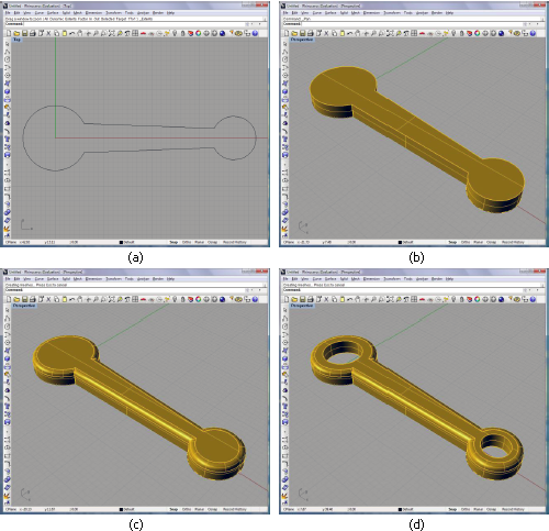
Fig. 1. Solid modeling in Rhino: (a) creating a 2D contour, (b) extruding it to make a solid, (c) blending its edges, and (d) adding holes
There is, however, a strong difference between Rhino and other MCAD systems, such as Pro/ENGINEER and SolidWorks, in how models are edited. In Rhino, for example, it is not possible to change the diameter of holes by simply clicking on them. Rhino cannot change the radii of fillets. And when the initial 2D contour is edited, the 3D solid does not change. This type of behavior is unexpected by typical MCAD users, who would become rather disappointed in the software.
The reason of this behavior is very simple: while most MCAD systems are history-based, but Rhino is not. It does not remember changes, known collectively as design history, which is a common way to express the design intent. History is like a recipe: when you want to change something in the model, you first modify the recipe, and then the CAD system automatically rebuilds the model according to modified recipe. The recipe, or history tree, is usually implemented on top of dumb geometry, the so-called BRep (boundary representation) of a solid model.
The history-based approach is common throughout nearly all modern MCAD systems; but there is an alternative available that allows design intent to be expressed in history-free environments. The approach consists of applying geometric constraints, driving dimensions, engineering equations, and other declarative specifications on top of BRep. (For simplicity, we will use the word constraints for all of these.)
Constraints have nothing common with design history. They can be added to the model at any time: when you create the model and when you modify it. Moreover, you can add constraints to dumb geometry obtained from other sources: downloaded from public 3D model databases, imported from other CAD systems, translated from IGES/STEP files, and so on. The primary problem with history is that it cannot be added to existing models; history is only created as you create a new model. That’s why the history-based approach cannot work in many situations*.
Constraints are simpler than history trees because they have no order. All constraints are equal and all are satisfied simultaneously. This is very different from rebuilding a model using a history tree. At any time you can remove any existing constraints with no impact on other constraints, since all are independent of each other. Manipulation with unordered lists on independent entities is simpler: you easily sort and filter constraints by their name, type, and argument.
Some constraints, however, do have the same parameters as do features in history trees. These parameterized constraints are called “driving dimensions,” because they usually correspond to lengths, radii, distances, and angles of objects in models. Driving, because models can be driven with using parameters. For example, when you edit the value of a driving distance value, the model is automatically changed to satisfy the new value. This is different from the usual type of (driven) dimensions, which just measure objects, and are recomputed when you modify the geometry. You can link the parameters of driving dimensions and free variables with engineering equations, using both standard math functions and external procedures.
Summarizing, constraints are a powerful way to express your design intent in history-free environments. You can add, remove, and modify them easily. Naturally, you can combine them with other knowledge-based engineering features. In the remainder of this paper, we consider the LEDAS implementation of constraints through the Rhino Assembly plug-in.
* Some MCAD systems seem to use intelligent tools to restore history trees from dumb geometry, but they work properly only for typical models.
Assembly Design in Rhino with Constraints and Driving Dimensions
Assembly design is a typical application where constraints are commonly used, even in history-based systems. The Rhino Assembly plug-in is the first LEDAS Driving Dimensions application for McNeel & Associates’ Rhinoceros software. It was chosen as the first one, because the corresponding functionality is familiar to most MCAD users.
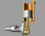
There are two well-known approaches in MCAD to assembling parts: top-down and bottom-up. In the top-down approach, you begin by designing an empty mechanism, and then create the geometry for its parts, one by one. You place them according to your design concept. By using this approach, you can design simple assemblies in Rhino, such as a piston engine. (See Fig. 2.)
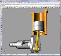
Fig. 2. A simple piston engine in Rhino
But the model contains no design intent, just as any other model in Rhino! For example, when you move the piston inside the cylinder, Rhino gives you the incorrect result shown in Fig. 3a: only one part was moved. The evident design intent, however, was to obtain the result illustrated by Fig. 3b, where translation of the piston implies the rotation of the crankshaft connected with the piston via the rod and a pin. How does one get this working correctly in Rhino?
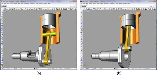
Fig. 3. Movement of the piston: (a) design intent is broken (default Rhino behavior), (b) design intent is kept with using Rhino Assembly plug-in
Imagine that you have the piston parts, either taken from a standard parts catalogue or designed just now. (See Fig. 4.) Instead of the top-down approach, in this case the bottom-up approach to assembly design should be employed: you position each part in 3D space with respect to the others. In Rhino, however, this is not very easy as it requires much manipulation by hand.
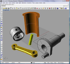
Fig. 4. How to assemble disjoint parts together?
How to keep the design intent intact when you move parts? How to simplify yet speed-up the bottom-up assembly process? Rhino Assembly plug-in clearly answers these questions. You can obtain a free 30-day evaluation copy from our Web site at www.DrivingDimensions.com.
After installing the plug-in, you will find the following new toolbar in the familiar Rhino environment:
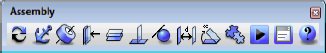
Fig. 5. Rhino Assembly toolbar
By using this toolbar, you can easily add geometric constraints between rigid parts. They can be appropriately placed in position, as shown by Fig. 2, or left scattered, as in Fig. 4.
Bottom-Up Design
Let’s begin first with the parts scattered, and then assemble the piston (see Fig. 6a). To put the pin inside the round hole of the piston, you need only three mouse clicks with Rhino Assembly plug-in:
- Click the “Add Concentricity” icon
 on the Assembly toolbar. on the Assembly toolbar.
- Click the cylindrical surface of the hole in the piston.
- Click the cylindrical surface of the pin.
When you click the “Add Concentricity” or similar icon, you are asked to select the arguments for the new constraint. Once you choose the arguments, the constraint is created and resolved immediately (simultaneously with other constraints already present in the model). After creating the concentricity constraint between the pin and the piston’s hole, Rhino immediately creates a placement similar to that shown in Fig. 6b, which can be then arranged to the final one (Fig. 6c), after applying a tangency constraint† between one flank of the pin and outer cylindrical surface of the piston (three more mouse clicks staring with “Add Tangency” icon).
The next step is to join the piston with the connecting rod. First add concentricity between the smaller round hole of the rod and cylindrical surface of the pin. You should use Rhino’s pan, zoom and rotate commands to simplify the selection process. The result should look like Fig. 6d.
The work remaining is to shift the rod along the pin to center it. For this, apply a coincidence constraint between the corresponding planar faces of the piston and the rod to make them mate each other (Fig. 6e). After a total of just twelve † Strictly speaking, the tangency constraint is not a correct choice here, because the ends of the pin will stick out of the piston; in the next section, we correct this problem using distance driving dimensions.
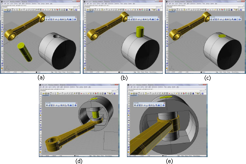
Fig. 6. Assembling piston: step by step
It is important to realize that the Rhino Assembly plug-in is much more than just a tool for placing rigid parts together easily. When you now move and rotate the piston (with Rhino’s transform commands), you see both the pin and connecting rod follow the piston correctly. It’s not a magic – it’s that you created a model that encapsulates not just geometry, but also design intent.
But the assembly is not yet finished, for the piston needs to be placed inside the cylinder. By now you should know how to do it. (If not, follow this step: apply the concentricity constraint between the outer surface of the piston and the inner surface of the cylinder.) Our Rhino Assembly plug-in considers all surfaces as infinite; if after this operation the piston is not placed in the cylinder correctly (as in Fig. 7a), move it to the desired position with the mouse. You now know that when you move the piston, all subparts (pin, rod) are moved together.
Now something more interesting occurs: when you move the piston, the cylinder is always concentric to it! This allows you to easily place the piston at the desired position along the cylinder. (See Fig. 7b.)
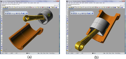
Fig. 7. Placing the assembled piston inside the cylinder
To place the crankshaft, apply a concentricity constraint between the smaller of its cylindrical surfaces and the large hole of the connecting rod. Move the crank along the hole (or apply a coincidence constraint between its flank and the planar surface of the rod). You may end up with a placement similar to one shown in Fig. 8a; this is incorrect, because the crank and the cylinder penetrate each other. To correct this problem, move either the piston or the cylinder to the desired position. Since the model contains design intent (as expressed through assembly constraints), any movement will be intelligent; i.e., the piston engine will not break into disjoint parts as you move parts relative to each other as you find the best positioning.
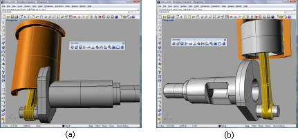
Fig. 8. Finishing steps in assembling the piston engine
To finalize the assembly, fix the cylinder and the rotation axis of the crankshaft. Click on the “Add Fixation” icon and select the cylinder. Then add another fixation constraint (this time select any cylindrical surface of the crankshaft except one already connected with the rod).
Managing Constraints and Driving Dimensions
To review the list of constraints added to the model, click the Show Assembly Manager icon in the Assembly toolbar, and then navigate through the window showed in Fig. 9. You may find it useful to dock this small window to one side of the Rhino window.
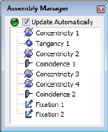
Fig. 9. Assembly Manager window
When you click on a specific constraint in the Assembly Manager, its arguments are highlighted automatically, including the geometric edges and faces connected with this constraint. This lets you see the design intent easily. Moreover, since constraints are stored with the model in its 3DM file, you can share the design intent with your colleagues; any of them who have the Rhino Assembly plug-in installed can open the Assembly Manager to see your design intent.
Assembly Manager not only shows which constraints were added to the model, but also edits them. The simplest edit is changing the constraint’s default name. For example, you may wish to rename “Concentricity 1” to “Piston-pin concentricity” – to simplify the transfer of knowledge from you to others who might use this model. To rename constraints, double click “Concentricity 1” in the Assembly Manager, and then edit the Name field. (The Constraint Properties window opens automatically; see Fig. 10.) While the Constraint Properties is open, you don’t need to double click the names of other constraints; one click is enough to edit. Again, you may dock the Constraint Properties window below (or above) the Assembly Manager window to easily access this tool in the future.
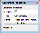
Fig. 10. Constraint Properties window
Assembly Manager can be used to remove constraints that are no longer needed, such as those that result from design intent changes. For example, when we put the pin inside the piston, we applied a tangency constraint between the flank of the pin and the outer cylindrical surface of the piston. This action, however, is a simplification, because a real pin would be placed completely inside the piston – pin parts that stick out scrape the side of the cylinder. We can correct this error: first, remove the tangency constraint by selecting it in the Assembly Manager, and then pressing the Del key on the keyboard. We will now replace the tangency constraint with a distance driving dimension.
Driving dimensions are another powerful tool introduced with the Rhino Assembly plug-in. Driving dimensions are similar to the geometric constraints described above (such as concentricity, tangency,
coincidence), but differ from them in one important area: they have parametric values. Let’s study the example of placing a distance driving dimension between the pin’s flank and the piston’s cylinder.
Click the Add Distance icon in the Rhino Assembly toolbar, and then select the same surfaces as before in the case of tangency constraint: the flank of the pin and the outer cylinder of the piston. You are prompted to enter the distance value; enter the desired value to immediately see the effect. (See Fig. 11.) in the Rhino Assembly toolbar, and then select the same surfaces as before in the case of tangency constraint: the flank of the pin and the outer cylinder of the piston. You are prompted to enter the distance value; enter the desired value to immediately see the effect. (See Fig. 11.)
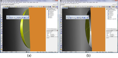
Fig. 11. Using Distance Driving Dimension to control the exact placement of the wrist inside the piston: (a) before, (b) after
If you don’t know the required value, accept the current one by pressing Enter key. You can later adjust it with the Constraint Properties window. When you select a driving dimension in the Assembly Manager, the window of Fig. 12 appears. Use the spin buttons on the right side of the Value field to adjust the values of dimensions. Each time you increase or decrease a value, the model is automatically updated to satisfy the new condition.
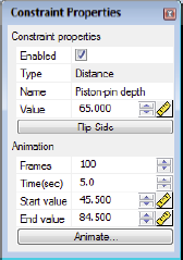
Fig. 12. Driving Dimension properties window
***
Let us summarize what we have learned about Rhino Assembly:
1. Rhino Assembly simplifies bottom-up assembly design. Your design work is sped up significantly, because you are able to assemble a piston engine in just a dozen mouse clicks!
2. Rhino Assembly adds design intent to dumb geometry. You have significant control over your design, because when you move parts, they move in accordance with the assembly constraints and driving dimensions you put between them. Mechanisms remain assembled; they never explode into disjoint parts.
The Rhino Assembly plug-in supports broad range of geometric constraints and driving dimensions: fixation, concentricity, coincidence, parallelism, perpendicularity, tangency, distance, angle, and rigid set. It is not possible to cover all of them in one paper, and so readers are welcome to find a detailed description of each tool at www.DrivingDimensions.com/Rhino/help.php.
At this point we have not yet listed all the advantages of Rhino Assemblies. We continue to do so in the next section.
Kinematic Simulation
When you design mechanisms in Rhino and other MCAD software, most likely you want to see them in action. Most mechanisms contain moving parts, and so an important part of the design process is to watch their trajectories as they move – before they are manufactured! You may find that some trajectories are not possible, because parts clash with each other or because of incorrect geometry. In this case, you must edit the part geometry or change the placement of parts inside the assembly.
The Rhino Assembly plug-in simulates the kinematics of mechanisms. In this section, we explain how using the same example of the piston engine.
To force the crankshaft to rotate about its axis, add an angular driving dimension to control the angle of rotation. To proceed, click the Add Angle icon on the toolbar, and then select the planar face on the crank and bottom planar face of the cylinder. (See Fig. 13.) Before accepting the proposed value, select the axis for the angle. Ordinary 3D angles between two planes can be measured between 0° and 180° only; if an axis is orthogonal to both planes, the angle between them can be in the range of 0° to 360°. To select an axis, enter “c,” and then select the cylindrical (rotational) surface of the crankshaft. Finally, enter the desired value for the angle.
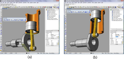
Fig. 13. Creating angular driving dimension between the engine parts (a) and changing its value (b
)
After placing the angular driving dimension, you can edit its value using the keyboard or the dialog box’s spin buttons. Immediately, the mechanism reacts to the changes. However, the better way to see mechanisms in action is by employing the Rhino Assembly plug-in’s animation feature.
Animations vary the value of driving dimensions at given intervals and steps, automatically repositioning parts according to the values. Animations take into account all constraints that express design intent in the model. Animations are recorded almost instantly, in background mode, and then can be replayed several times as you observe the mechanism in action.
The Constraint Properties window has an Animation section for driving dimensions (see Fig. 12). Two input fields specify the number of frames and the animation’s duration in seconds. The other values required for this example are the start and end angles; let’s enter 0 and 360 for the angle. Click Animate at the bottom of the Constraint Properties window to see the slider window of Fig. 14. Its controls are familiar to anyone who has used software video or audio players. When you press the Start button (blue triangle), the animation is replayed immediately. You can press the Pause button at any time to halt the animation. The controls allow you to view the initial or final frames directly, as well as jump to the next or previous frames. Check the Repeat box to loop the animation endlessly (until you stop it).
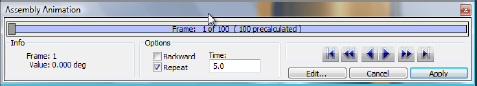
Fig. 14. Assembly Animation window with slider
An important aspect of the Rhino Assembly plug-in is the ability to apply the pan, rotate and zoom commands during animation. This allows you to see the animation in 3D from any point of view; the viewpoint can be dynamically modified by the user at any time during the animation. This function provides a lifelike experience of the kinematics in your mechanism.
***
Let’s add to the list of added-value summary of the Rhino Assembly plug-in begun in the previous section:
3. Rhino Assembly simulates the kinematics of mechanisms with movable parts. With driving dimensions, you can control the relative positions of parts, automatically and in real time.
4. Rhino Assembly animates lifelike experiences. You can repair and improve mechanisms before manufacture.
To learn more about the animation feature of the Rhino Assembly plug-in, please visit our help page at www.DrivingDimensions.com/Rhino/help.php to find a detailed description of each tool.
What’s Next
The preliminary beta version of Rhino Assembly plug-in was launched in June 2009 under the trade name of “Driving Dimensions for Rhino.”14. Since then, more than 3,000 Rhino users downloaded it from www.DrivingDimensions.com. LEDAS developers appreciated the useful comments made by Rhino users, resellers, and McNeel’s own experts, and the result was version 1.0 released in November 2009. Some ideas are waiting for version 2.0, which will be released in 2010. But there is something special that is needs to be announced now.
As we noted, the Rhino Assembly plug-in works with rigid parts; it does not modify the geometry internal to parts. It just places all parts relative to each other through translation and rotation. In some cases, however, this is not enough. For instance, we may need to modify the length of the connecting rod in our piston engine to avoid collisions.
To make changes intelligently means modifying Rhino’s 3D geometric shapes yet keeping their design intent. We will provide the answer in Part II of this white paper. In it, we will present a Rhino plug-in for history-free 3D geometry editing using the same geometric constraints and driving dimensions. We plan to release the first public beta by the end of 2009 at www.DrivingDimensions.com.
About the Author
 Dr. Dmitry Ushakov has 15 years of experience in computational software development with different applications in the CAD domain. Dr. Dmitry Ushakov has 15 years of experience in computational software development with different applications in the CAD domain.
Dr. Ushakov graduated from the Novosibirsk State University in 1993, specializating in mathematics and applied mathematics. In 1995, he received his Masters of Mathematics degree, and in 1998 received his PhD degree in Computer Science from the same university.
Prior joining to LEDAS, Dr. Ushakov worked as a scientist at the Russian Research Institute for Artificial Intelligence. His primary interests were in the areas of theoretical foundations of constraint programming and the development of computational software for solving broad ranges of constraint satisfaction problems in various domains. From 1999 to 2001, Dr. Ushakov was temporarily assigned to Dassault Systemes, a world-leading CAD/CAM/CAE software company, where he worked on the development of a core mathematical solver and end-user components for the CATIA V5 system of knowledge-based engineering software. During 2001-2008, he held the position of Chief Technology Officer at LEDAS, where he coordinated software development projects aimed at creating constraint solvers for geometric and engineering problems.
Since 2008, Dr. Ushakov is Product Management Director at LEDAS. He is the author of more than 50 scientific papers.
About LEDAS
LEDAS Ltd. is an independent software development company founded in 1999; it is based in the Novosibirsk Scientific Centre at Akademgorodok, the Siberian Branch of the Russian Academy of Science. A leader in constraint-based technologies, LEDAS is a well-known provider of computational software components for PLM (Product Lifecycle Management) solutions: geometric constraint solvers for CAD/CAM/CAE, optimization engines for project management, work scheduling and meeting planning as well as interval technologies for knowledge-based engineering and collaborative design. The company also provides services for PLM markets: software development, consulting, reselling as well as education and training. More information about LEDAS is available at www.ledas.com.
1 Rhinoceros® NURBS modeling for Windows. http://www.rhino3d.com/
2 Interview with Robert McNeel, CEO of McNeel and Associates (Rhino 3D). http://blog.novedge.com/2007/03/an_interview_wi_3.html
3 openNURBS™ Initiative. http://www.opennurbs.org/
4 Rhinoceros - Related Products and Services http://www.rhino3d.com/resources/
5 LEDAS Geometric Constraint Solver LGS 3D Is Licensed By Joe Gibbs Racing http://ledas.com/group/press_releases/?press_num=119
6 CD-adapco licenses LEDAS variational geometric solver LGS 2D http://ledas.com/group/press_releases/?press_num=107
7 Swiss AVW Company succeeds with LEDAS geometric solvers http://ledas.com/group/press_releases/?press_num=69
8 LEDAS enters CAM/CNC market in partnership with Tecnos G.A. Srl. http://ledas.com/group/press_releases/?press_num=58
9 ADEM Technologies releases its new integrated system, ADEM 8.0, with LEDAS geometric solver LGS 3D http://ledas.com/group/press_releases/?press_num=24
10 LGS 2D – two-dimension variational solver from LEDAS is licensed by Proficiency http://ledas.com/group/press_releases/?press_num=3
11 Dmitry Ushakov. Variational Direct Modeling: How to Keep Design Intent in History-Free CAD. LEDAS White Paper. http://ledas.com/group/white_papers/
12 LGS 2D, LEDAS Geometric Solver. http://ledas.com/products/lgs2d/
13 LGS 3D, LEDAS Geometric Solver. http://ledas.com/products/lgs3d/
14 LEDAS Announces Beta Release of Driving Dimensions Plugin for Rhino http://drivingdimensions.com/news.php?num=8
Permanent link :: http://isicad.net/articles.php?article_num=13430

|
 |