|
Articles
29 Sep 2010 Adding Intelligence to Direct ModelingDmitry Ushakov During the plenary session of the COFES-Russia/isicad-2010 forum held in Moscow on September 21, 2010, Dmitry Ushakov gave a five-minute talk on the topic of direct modeling in computer-aided design systems. A PDF of the original PowerPoint slides can be downloaded here; the extended version of his presentation is given below.
Did you ever think about how easy is to make changes to 3D geometry? Indeed, it is easy if you...
- Spend a lot of money to license and maintain a mainstream MCAD system
- Take enough time to learn its parametric feature-based modeling methodology
- Use only the one CAD system to create and modify geometry
- Find the parameters you want to change listed in the feature tree
...then you are lucky, and editing is quite easy. But what if at least one of the above conditions is false? In that case, it could be that direct modeling would be beneficial to you.
In direct modeling (DM) systems, you deal with geometry directly, not indirectly through a feature tree. This means you can directly manipulate 3D models through their boundary entities – faces, edges, and vertices. You can move and deform them interactively, or else use driving dimensions to position them accurately. This untethered editing capability allows you to modify any geometry, independent of its source - whether from its own CAD system or imported from another. Moreover, there is a cost savings to you, as DM systems are usually significantly cheaper than mainstream feature-based MCAD packages.
Too much marketing spice? Not at all. These are all true advantages of DM systems. There is, however, just one fly in the ointment: "no features" means no design intent, and almost any operation will modify your model in way that you may not want.
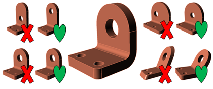
To preserve design intent, the modeling system should support user modifications in an intelligent manner, by moving and changing related elements appropriately. Most DM systems are not able to address this issue, while others support only the simplest of cases. Check your DM system to see whether is can make the modifications illustrated in the following figure:
Existing approaches tend to consist of step-by-step modifications or multi-selections (with smart patterns). These are error-prone, however, and do not help very much, because they are useful only in simple editing.
Variational Direct Modeling
A promising and powerful solution is the automatic recognition of design intent, which then converts intent into a set of geometric and dimensional constraints on the boundary elements of the featureless model. Computer systems can easily recognize 3D geometry relationships, such as coincident, tangent, parallel, perpendicular or coaxial faces, equal distances, radii and angles between elements, and symmetry. (Additional constraints can be added by the user.) All constraints are solved simultaneously and the boundary geometry is updated by moving its boundary faces. We call this concept "variational direct modeling" (VDM).
Constraints can specify and control design intent, although users still need the ability to recognize features in history-free models, such as to remove or copy holes, fillets, and pockets. A powerful VDM system should be able to recognize simple features that do not depend on each other, and allow users to remove/copy any of them. But it also should recognize geometric constraints and solve them each time the model is changed by the user.
Constraints are easy to use, because they have no order or dependency. This means that any constraint can be removed at any time, with no impact on the rest of the model. The user creates only those constraints and driving dimensions that are needed for the parametric modification of the model: in most cases, just few dimensions are needed. (Compare this with feature-based approaches, where the system places tons of useless parameters in the feature tree.)
Constraints are easy to learn; indeed, they are not new to MCAD users, who deal with them in parametric drawings/sketches and in assembly design applications. VDM is a logical and consistent application of the same concept to 3D geometry editing. Geometric constraints represent basic geometric concept (parallelism, perpendicularity, tangency) and don’t need to be explained. Driving dimensions generalize the well-known notion of reference dimensions, and so users learn them quickly.
Solving constraints is scalable and robust procedure. All constraints of one model (as defined by the user and recognized automatically) have to be solved simultaneously. A naïve approach would consist of solving a system of nonlinear equations; this does not work, even for moderate-sized models. In most cases fortunately, a constraint problem can be decomposed into a set of smaller ones; by solving them one by one, it is possible to find the solution to an initially large problem. Usually, it takes less than one second to solve a model with one thousand constraints.
VDM is easy to implement, for it consists of just three parts:
- The core of VDM is a geometric constraint solver, a software component that is able to solve large-scale constraint problems efficiently.
- Another part is the important ability of VDM to recognize geometric relationships between elements of the model, and then convert them into a non-contradictory set of constraints. (The result should be tuned by the user.)
- The third part of VDM is its geometric modeling kernel, which is needed to modify BReps [boundary representations] after all constraints are solved.
Fortunately, CAD vendors don't need to develop these components in-house; it is sufficient to license existing solutions from technology component providers. Here at LEDAS, we are ready to help CAD developers to implement VDM technology in their applications.
About LEDAS Technology Components
LEDAS has been developing its original constraint solving technology since 2001. The result is a component known as LGS, short for LEDAS Geometric Solver. It has been licensed by a dozen CAD/CAM/CAE vendors, who have successfully implemented parametric drawing, assembly design, and motion simulation applications on top of it.
Our new VDM technology is the evolution of LGS. It is already implemented in a series of end-user applications under our "Driving Dimensions" brand name. These applications consist of plug-ins for popular 3D modeling software packages , such as SketchUp and Rhinoceros.
With Driving Dimensions, 3D models become smarter: when you move a part, the other parts are moved in accordance with it. When you modify a driving dimension, geometric shapes are not simply scaled, but actually change their form according to your design intent.
Visit DrivingDimensions.com to learn more about this technology and download the applications.
See also:
Permanent link :: http://isicad.net/articles.php?article_num=14006

|