|
Articles
16 Jan 2018 INTRODUCING PARAMETRIC MODELING 2.0Jon Hirschtick
2018 marks the 30th anniversary of parametric feature-based CAD (for trivia buffs, the first viable parametric feature-based CAD system was Pro/ENGINEER from PTC, introduced back in 1988). This year also marks the emergence of a new generation of parametric modeling that we call “Parametric Modeling 2.0,” incorporating all the power of the older generation, but also extending and improving it in several key areas.
Onshape’s newest contributions to Parametric Modeling 2.0 are modern reboots of Configurations and Standard Content, but before we explore those new features, let’s briefly revisit why 1988 was so wonderful for CAD users.
On the most basic level, the beauty of feature-based parametric modeling was that engineers could create solid models with an ordered list of understandable modeling features (sketch, extrude, fillet, shell, etc.) and, by changing dimension values – or adding, editing, reordering or deleting features – their solid part’s geometry would automatically update. Parametric Modeling 1.0 made solid modeling practical for the first time and was a huge time-saver.
Using an ordered list of parametric features to make a part worked really well, and continues to work well today. But there were a bunch of weaknesses at the edges of parametric modeling: tools that people really wanted to use, but found they did not work very well; or tools they were even afraid to use because they were kludgy and unreliable. These weaknesses included in-context design, multi-part design, custom features and configurations.
The kludgiest of the kludgy parametric tools was in-context design. Old parametric modeling offered the powerful promise of designing parts in the context of an assembly, but unfortunately in-context design never worked very well in older parametric modelers. Changing or moving a part often caused unpredictable geometry changes and broken CAD models, problems that occurred so frequently that many companies literally banned the use of in-context references altogether!
Those who still take the risk soon regret it. An engineer at a radiation detection company recently told me he watched the holes on a back panel of an assembly “unexpectedly float around” the last time he tried in-context design with his old parametric CAD system. Needless to say, whether you’re designing a radiation detector or a ballpoint pen, models should not have minds of their own.
SIX WAYS PARAMETRIC MODELING 2.0 IS FUNDAMENTALLY BETTER
All of the core elements of Parametric Modeling 2.0 existed in some form in Parametric Modeling 1.0. The difference is that they were clunky at best (like those shaky cup holders that used to hang on car windows) – and unusable or dangerous at worst (think about those hoverboards that catch on fire).
Parametric Modeling 2.0 ushers in fundamentally better ways of modeling in many areas such as:
- Multi-Part Design
- Configurations
- Standard Content
- Managed In-Context Design
- Simultaneous Sheet Metal Tools
- Custom Features
Let’s take a closer look at each of these aspects of Parametric Modeling 2.0.
1. MULTI-PART DESIGN
Let’s be frank: Creating multiple parts at the same time in old CAD systems has been kind of a chewing-gum-and-duct-tape experience. Yes, it can be done (eventually), but old multibody parts approaches are really tough and laborious to use. When you create multiple parts, you have to define a separate feature history for each one. You can define a single part with multiple “bodies,” but you can’t define true multiple parts driven by a single parametric history. This may seem subtle, but in practice it is a huge distinction. Onshape has extended the power of parametric design from one part at a time to multiple interrelated parts that are naturally treated independently in assemblies, BOMs and downstream applications.
In Onshape, if you want to drill a hole through two parts, no problem. Or if you want to round all the edges at the interface between two parts, you can do that in one operation.
When using multibody techniques in old CAD, you have to do it twice. If you then want to put these parts in an assembly and use them as independent parts, you can't do it directly. Because in old CAD, a part has to be a file. So we have to do a derived part in two separate files with each body. You end up with all these extra intermediate files that you need to maintain to use the two parts in your assembly.
In Onshape’s Multi-part Part Studios, all parts related to one another are designed together in one place, where it most makes sense. This enables you to use the power of a single parametric history to build robust relationships between multiple parts and to enable true top-down design. By defining common features and inter-part relationships in one place – instead of bouncing back and forth between files – you can ensure that the results of your design changes are predictable and robust.
Multi-part design is now a much smoother experience.
2. CONFIGURATIONS
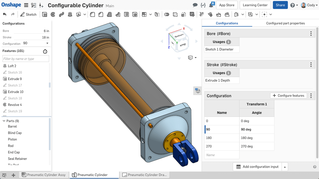
Configurations are a way to create variations of parametric models involving different sets of parameters and other options that you can switch between very easily. So a simple example would be configuring a phone in two sizes: Plus and Regular.
Old CAD systems require all configuration options to be represented in a single table with entries for each conceivable permutation, which in some cases can lead to thousands of rows in that single table. As configurations get more complex with more options, that table grows exponentially – making it virtually impossible to understand, troubleshoot or manage.
Onshape’s approach focuses on making it manageable for users to build and use the sophisticated configurations that modern designers often need. To do this, Onshape lets you build complex families of parts by creating separate small tables for each set of independent configuration options. This dramatically reduces the number of required table rows and cells. No more monster tables. For example, in old CAD, a simple bracket with 5 lengths, 5 heights and 5 hole patterns would result in an enormous 375-cell table to manage in a clumsily embedded Excel spreadsheet. In Onshape, this same configuration results in 3 tables of only 5 cells each and is edited with a native intuitive user experience.
The second major difference is what you can configure. Using old CAD systems, you could only configure certain things, such as specific dimension values and feature suppressions. With Parametric Modeling 2.0, you can configure practically everything, including things like continuous values and even entity selection sets.
The third major difference is when configurable parts are inserted into assemblies. In old CAD, users are forced to navigate a long list of text string names, one for every possible permutation, with none of the original configuration options visible. In Onshape, users are presented with a clean and straightforward menu offering the original configuration options, making it easy to find the permutation they need.
3. STANDARD CONTENT
Old CAD systems have add-ons for standard fastener content that cause two major problems for users. The first problem is that the fastener parts have very limited automation for fitting themselves into assemblies and stackups of fastener parts, etc.
In Onshape, each fastener has a built-in mate connector, making standard content smarter and making positioning in assemblies much easier. Onshape has added the “fit” to “form, fit and function.”
You can easily create "stacks" of fasteners, such as bolt-washer-washer-nut, in any order you like. As you add any new fastener anywhere within a stack, the other fasteners shift to accommodate it without requiring you to manually delete, create or debug mates.
Standard content is presented to you right inside Onshape’s assembly insert dialog so you don't have to go hunting for it, download it, check out the license for the add-in, etc. You also don't have to manage these libraries – they are just there and ready to use when you need them – and you’re able to add your own company part numbers.
Because many old parametric CAD systems treat standard fastener content as an optional add-on module, colleagues and suppliers often run into problems working with assemblies containing standard content. The reason is either they don’t have a license code for that add-on, or each person’s copy of the standard content files has their own differing metadata.
Standard content now is very easy to position and share with an entire team.
4. MANAGED IN-CONTEXT DESIGN
Most CAD systems offer users the ability to add in-context relationships between parts in the context of an assembly so modifying one part will affect another. Unfortunately, changing in-context parts or their parent assemblies in old file-based CAD systems will often erroneously change other parts in unpredictable ways.
This maddening event occurs because multiple relationships are stored in separate files and it is difficult to manually keep track of how they are all interrelated. Even a simple movement of a mechanism can cause the shapes of the parts to change in unanticipated ways.
Designers are absolutely helpless in this situation. They have zero control over how and when these complex relationships update: sometimes they recalculate when a part is rebuilt, sometimes when the assembly is updated, and sometimes because a seemingly unrelated part file was edited and saved sometime in the past.
Many companies that use old CAD systems outright ban the use of in-context relationships because of this unpredictability. Some old CAD tools even include a user-defined setting that will prevent the use of in-context relationships.
With its unique database architecture, modern Onshape has solved all these problems. Using Onshape’s Managed In-Context Design tools, CAD models always update in a predictable, controlled manner against immutable historical snapshots of the assembly.
Also, motion no longer affects in-context relationships. You can now use multiple assembly contexts to edit single or multiple parts, and you can update the assembly context (the state of the assembly) if needed. And remember, even when you make a mistake, Onshape allows you to always go back to any prior state of your model – something no other CAD system can do.
It’s finally safe to end the ban on in-context relationships!
5. SIMULTANEOUS SHEET METAL TOOLS
Unlike old CAD systems that calculate flat, folded and tabular sheet metal representations in three separate unsynchronized views, Onshape computes and displays all representations simultaneously. When you edit one view, the other two are synchronized automatically using Onshape’s secure cloud architecture. Seeing the flat and folded views side-by-side allows you to visualize errors and interferences immediately.
By also allowing editing in the Table View, the designer or even the downstream manufacturer can quickly change things such as bend radii, bend order or even convert bends to rips and vice versa. When you make a change in the table, you immediately see the impact on both flat and folded views. Old CAD systems require laboriously rolling back, suppressing, deleting and adding features to make similar changes and see their impact.
6. CUSTOM FEATURES
Ever wish you could change the way your CAD system’s features work? Old CAD systems all offer some form of macro programming language or API to let you create custom features, but they are never as good as the built-in ones.
Onshape has developed a programming language called “FeatureScript” that has been used to create all of Onshape’s built-in features, such as extrude and shell. This programming language enables every user to build custom features that appear and behave exactly like built-in features and are treated as first class citizens. This gives them the intelligence to understand their surroundings so as changes are made, the feature geometry updates accordingly. FeatureScript makes it easy to build robust, industry-specific CAD features that you wouldn’t normally find as standard in a CAD system.
As one of our customers, a luxury cabinet manufacturer, recently put it, “We’re essentially programming our own CAD system designed specifically for cabinet making… A core value of our company is that we develop our own systems versus bringing in consultants to develop solutions for us. The fact that we can code and develop within Onshape makes it a really good fit for us.”
With FeatureScript, it’s like the CAD company built a parametric modeling system just for you, with features made specifically for your work. That’s the way things should be. That’s Parametric Modeling 2.0.
Before Onshape, the only way to add new built-in features to your CAD system was to submit an enhancement request to your CAD vendor – and wait months, years or forever for your wish to be granted. With FeatureScript, you can create built-in CAD features right now and share them securely with anyone you choose.
THANK YOU
Again, Onshape didn’t invent parametric modeling, but we have fundamentally improved it. If you love the idea of hopping on a hoverboard, you should be able to focus on your balance and riding technique. You shouldn’t have to worry about it exploding. Similarly, if you want to define multiple parts top-down with a single parametric history or add in-context relationships between parts in an assembly, you shouldn’t have to worry about your assembly exploding.
I’ve devoted my entire professional life to advancing CAD technology and I’m proud of Onshape’s role in modernizing parametric modeling to better help you do your best work. Thank you to the many customers who shared incredible ideas and feedback that helped us develop every aspect of Parametric Modeling 2.0.
Permanent link :: http://isicad.net/articles.php?article_num=19641

|